Ventilation device for building design

A technology of ventilation device and architectural design, applied in ventilation system, space heating and ventilation, application, etc., can solve problems such as affecting the health of indoor personnel, accelerated breathing, poor air quality, etc., to improve the user experience and ensure the cleaning effect. , the effect of reducing energy consumption

Inactive Publication Date: 2022-05-17
李青
View PDF0 Cites 0 Cited by
  • Summary
  • Abstract
  • Description
  • Claims
  • Application Information

AI Technical Summary

Problems solved by technology

[0003] With the development of the times, due to the high building density and dense population per unit area of ​​modern buildings, mechanical ventilation is often used to achieve building ventilation. Traditional building ventilation uses axial flow fans to extract indoor air. Doors and windows take in fresh air. However, modern buildings consider thermal insulation design and have good airtightness. At the same time, air conditioners and other temperature control equipment are often used indoors, and windows will not be opened, resulting in poor ventilation. On the other hand, modern buildings have a high density. , when the windows are not opened, the air is often inhaled through the door cracks located in the corridor, resulting in poor quality of the inhaled indoor air, which cannot achieve effective ventilation and ventilation, and eventually causes high carbon dioxide content in the indoor air, causing people in the room to breathe. Discomfort such as acceleration, fatigue and powerlessness will also affect the health of indoor personnel in this environment for a long time. Therefore, we propose a ventilation device for architectural design to solve the above problems

Method used


Image

  • Ventilation device for building design
  • Ventilation device for building design
  • Ventilation device for building design

Examples


Embodiment Construction

[0030] The following will clearly and completely describe the technical solutions in the embodiments of the present invention with reference to the accompanying drawings in the embodiments of the present invention. Obviously, the described embodiments are only some, not all, embodiments of the present invention.

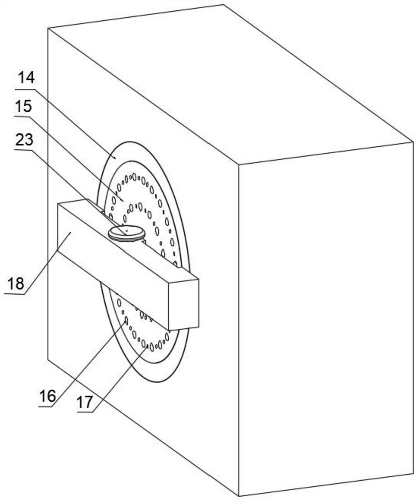
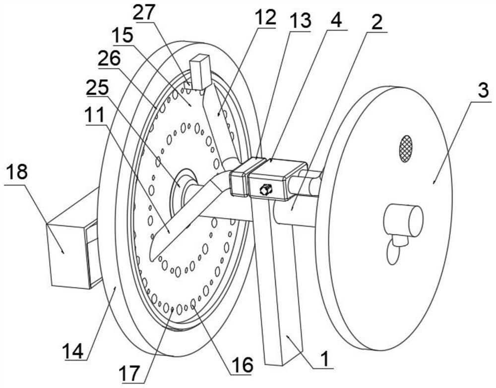
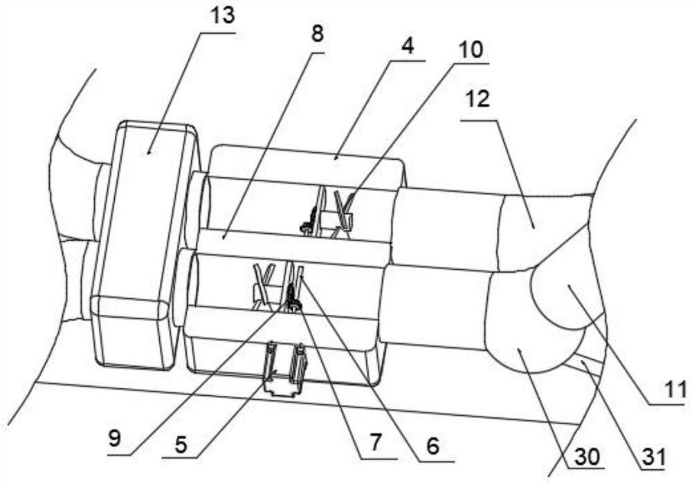
[0031] refer to Figure 1-3 , a ventilation device for architectural design, including a channel opened on the wall, a support rod 1 is fixedly connected to the channel, and a round pipe 2 is fixedly connected to the upper end of the support rod 1, and the round pipe 2 is provided with There is a ventilation component, and one end of the round pipe 2 is fixedly connected with an outer panel 3, which is located outside the building wall, and can be installed with outdoor decoration according to the appearance of the building without blocking the air inlet and outlet , so as to ensure the aesthetics of the outer wall of the building, only a part of the round tube 2 is ...


PUM


Abstract

The invention discloses a ventilation device for building design, which comprises a channel formed in a wall body, a supporting rod is fixedly connected in the channel, a round pipe is fixedly connected to the upper end of the supporting rod, a ventilation assembly is arranged on the round pipe, an outer plate is fixedly connected to one end of the round pipe, and an inner plate assembly is arranged at one end, away from the outer plate, of the round rod. The ventilation assembly comprises a shell fixedly connected with the supporting rod. According to the air exchange device, by arranging the air exchange assembly, outdoor fresh air is injected into a room while indoor polluted air is pumped out through the air inlet pipe and the air outlet pipe which face different directions, practical requirements of modern buildings are met, meanwhile, the problem that the ventilation effect is poor due to air short circuit is solved, and the air exchange device is compact in structure and convenient to use. An axial flow fan in an existing building can be directly transformed into the ventilation device, and the outer wall of the building does not need to be constructed.

Description

technical field [0001] The invention relates to the technical field of construction engineering equipment, in particular to a ventilation device for architectural design. Background technique [0002] Building ventilation is divided into natural ventilation and mechanical ventilation. It means that the dirty air in the building is directly or purified and discharged to the outside, and then fresh air is added in, so as to keep the indoor air environment in line with hygienic standards. Its purpose is to ensure the elimination of indoor pollutants, ensure the thermal comfort of indoor personnel, and meet the needs of indoor personnel for fresh air. On the other hand, the temperature has a great relationship with indoor odor. If there is no uncomfortable feeling, then each person in the room needs 30m per hour 3 fresh air, and when the indoor temperature rises to 30°C, if people do not feel uncomfortable about the smell, each person in the room needs 50m per hour 3 of fresh ...

Claims


Application Information

Patent Timeline
Patent Type & Authority Applications(China)
IPC IPC(8): F24F7/10
CPCF24F7/10Y02B30/70
Inventor 李青
Owner 李青
Why Eureka
Try Eureka