
Input redundant power supply circuit and control method thereof

A technology of redundant power supply and relay circuit, which can be used in circuit devices, emergency power supply arrangements, high-efficiency power electronic conversion, etc., and can solve problems such as electrical contact wear and tear.

Pending Publication Date: 2022-05-17
FLEX LTD
View PDF0 Cites 0 Cited by
  • Summary
  • Abstract
  • Description
  • Claims
  • Application Information

AI Technical Summary

Problems solved by technology

More specifically, this instantaneous current may exceed the tolerance of the relay switch, and the electrical contacts of the relay switch may wear due to the opening and closing of the relay switch

Method used


Image

  • Input redundant power supply circuit and control method thereof
  • Input redundant power supply circuit and control method thereof
  • Input redundant power supply circuit and control method thereof

Examples


Embodiment Construction

[0013] Embodiments of the present invention are described below in conjunction with an input redundant power supply circuit.

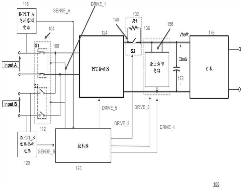
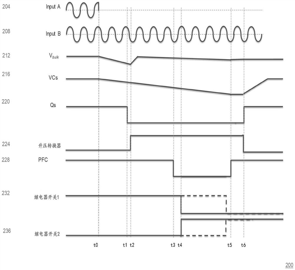
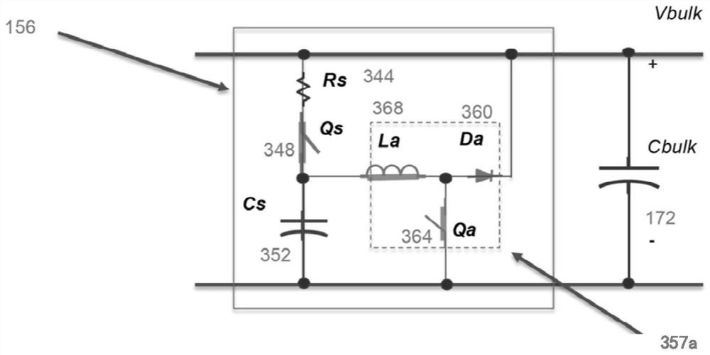
[0014] figure 1 A schematic diagram of an input redundant power supply circuit according to an embodiment of the present invention is shown. The input redundant power supply circuit 100 includes an automatic transfer switch (ATS) relay unit 104, an INPUT_A voltage sensing circuit 116, an INPUT_B voltage sensing circuit 120, a power factor correction (Power Factor Correction, PFC) converter 124 and a controller 128, The ATS relay unit 104 includes relay circuits 108, 112, the relay circuit 108 having a relay switch S1, and the relay circuit 112 having a relay switch S2. Relay circuit 108 is coupled to input voltage INPUT_A, and relay circuit 112 is coupled to input voltage INPUT_B. It should be noted that the input voltage INPUT_A and the input voltage INPUT_B can be two AC input voltages, one AC input voltage and one high voltage DC input voltage (su...


PUM


Abstract

An input redundant power supply circuit includes a power converter, a relay switch unit including a first relay circuit coupled to a first power supply and a second relay circuit coupled to a second power supply, a control unit configured to control the relay switch unit and cause the power converter to be powered by the first power supply or the second power supply, a bulk capacitor powered by the power converter, and a boost converter coupled between the power converter and the bulk capacitor. When the relay switch unit is switched from one of the first power supply and the second power supply to the other of the first power supply and the second power supply, the boost converter maintains a voltage across the large-capacity capacitor higher than a voltage of the first power supply or a voltage of the second power supply. Therefore, zero-current switching is realized.

Description

technical field [0001] The present invention generally relates to power switching in power distribution systems, and more particularly to input redundant power with automatic transfer switch (ATS) circuits and control methods. Background technique [0002] Relay switches in power distribution systems are operable to selectively energize or interrupt power to loads. When one of the power sources becomes abnormal, the relay switch switches from the abnormal power source to another power source to continue supplying power to the load. During the switching process of the relay, since the input voltage provided by the power supply is greater than the output voltage, a high instantaneous current may be generated, such as surge current or high surge current. More specifically, this instantaneous current may exceed the tolerance of the relay switch, and the electrical contacts of the relay switch may wear due to opening and closing of the relay switch. Contents of the invention ...

Claims


Application Information

Patent Timeline
Patent Type & Authority Applications(China)
IPC IPC(8): H02J9/06H02M1/32
CPCH02J9/06H02J9/068H02M1/32H02M3/156H02M1/36H02M3/33507H02M1/007H02M1/10H02M1/4208Y02B70/10
Inventor 许化民严伟加
Owner FLEX LTD
Learn More