Driven reel

A technology for pulling grain wheels and sprockets, which is applied in the direction of belts/chains/gears, hoisting devices, mechanical equipment, etc., which can solve the problems of easy damage to bearings and poor combination accuracy, so as to optimize the space structure, improve bearing capacity, and improve The effect of combined precision

Pending Publication Date: 2022-05-20
浙江博盟精工轴承有限公司
View PDF0 Cites 0 Cited by
  • Summary
  • Abstract
  • Description
  • Claims
  • Application Information

AI Technical Summary

Problems solved by technology

[0003] The invention aims at the disadvantages of easy damage of bearings and poor combination precision in the prior art, and provides an integrated follower puller

Method used


Image

  • Driven reel
  • Driven reel
  • Driven reel

Examples


Embodiment 1

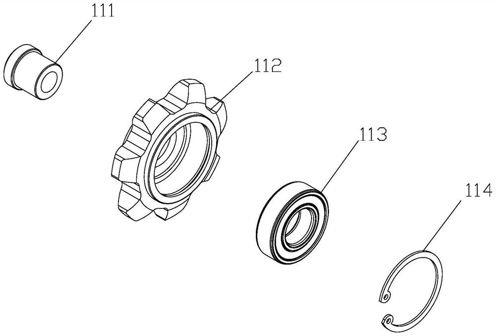
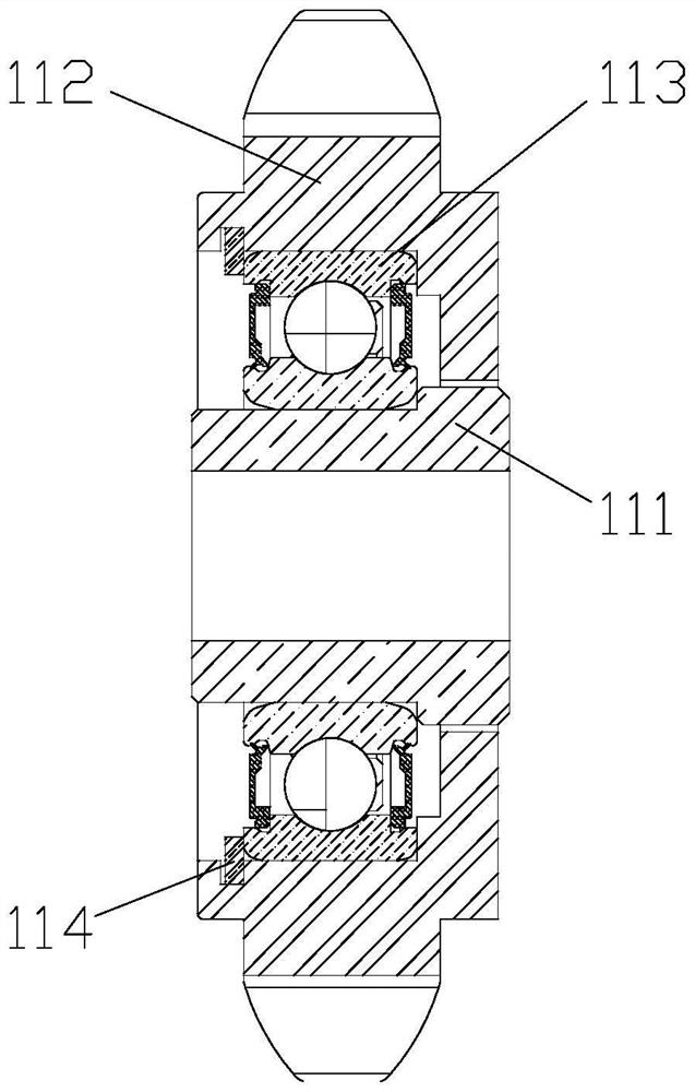
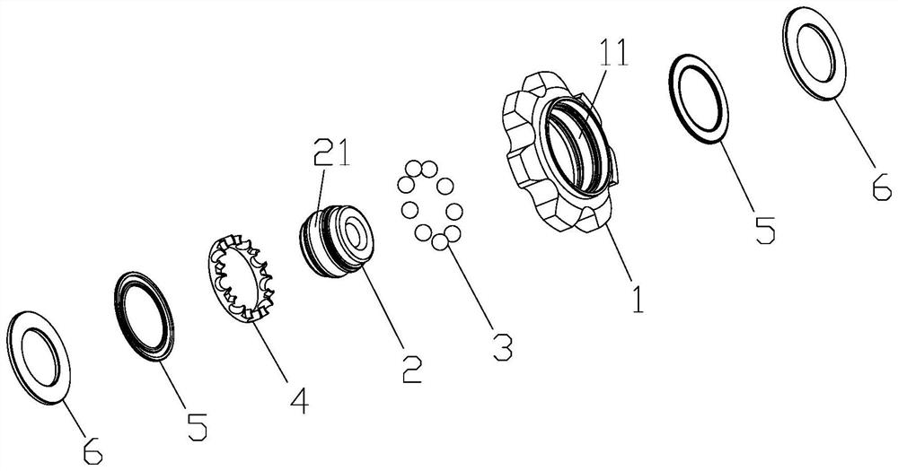
[0032] The driven pulling wheel includes the pulling wheel body, the pulling wheel body is the sprocket outer ring 1, and the inner hole wall of the sprocket outer ring 1 is provided with the first channel 11; it also includes the sprocket inner ring 2, the sprocket inner ring The outer wall of the ring 2 is provided with a second channel 21; the second channel 21 of the sprocket inner ring 2 cooperates with the first channel 11 of the sprocket outer ring 1 to form a channel space, and steel balls are placed in the channel space 3. The inner hole of the sprocket inner ring 2 is the shaft hole 9. It also includes a cage 4, which evenly separates the steel balls 3.

[0033] The reel body is transformed into the outer ring of the sprocket, that is, the structure of the outer ring of the bearing. At the same time, the inner ring of the sprocket is matched to save the bearing parts. At the same time, the channel space formed by the inner and outer rings of the sprocket is enlarged ...

Embodiment 2

[0035] On the basis of Embodiment 1, a sealing member 5 and a dustproof member 6 are arranged between the sprocket outer ring 1 and the sprocket inner ring 2 , and the dustproof member 6 is located outside the sealing member 5 . The dustproof part 6 is in interference fit with the outer wall of the sprocket inner ring 2, and is in clearance fit with the inner hole wall of the sprocket outer ring 1. A double-layer sealed and dust-proof structure is set. On the basis of the seal, a dust-proof piece 6 is added to protect the channel space. At the same time, the double-layer sealed and dust-proof structure is an independent double layer, and its strength and extrusion resistance are equal. very good.

Embodiment 3

[0037] On the basis of implementation 2, the sealing member 5 and the dustproof member 6 are in two groups, which are symmetrically arranged on both sides of the channel space. It further protects the channel space, effectively prevents the anti-mud effect of agricultural machinery, and can well block the sundries in the field from damaging the bearings, and the service life can be increased by at least 3 times.


PUM


Abstract

The invention relates to the technical field of bearings, in particular to a reel with a bearing structure. The driven reel comprises a reel body and is characterized in that the reel body is a chain wheel outer ring (1), and a first channel (11) is formed in the inner hole wall of the chain wheel outer ring (1); the chain wheel further comprises a chain wheel inner ring (2), and a second channel (21) is formed in the outer wall of the chain wheel inner ring (2). The second channel (21) of the chain wheel inner ring (2) is matched with the first channel (11) of the chain wheel outer ring (1) to form a channel space, the steel ball (3) is placed in the channel space, and an inner hole of the chain wheel inner ring (2) is a shaft hole (9). According to the technical scheme, the reel body is transformed into the outer ring of the chain wheel, namely, an integrated design is adopted, the combination precision is improved, the space structure is optimized based on the size of the reel, the used steel balls are enlarged, the wall thickness from the bottom of the channel to the inner ring is increased, and the bearing performance is improved. Meanwhile, a double-layer sealing structure is adopted, and the sealing performance is higher.

Description

technical field [0001] The invention relates to the technical field of bearings, in particular to a pulling wheel with a bearing structure. Background technique [0002] Bearing is an important part of mechanical equipment, which is widely used, especially the operation of the puller on the harvester is inseparable from the cooperation of the bearing, such as figure 1 with figure 2 As shown, the harvesting wheel 112 is placed on the outer periphery of the bearing 113 through the shaft sleeve 111, and the bearing 113 is fixed in the harvesting wheel 112 by the snap ring 114. The puller 112 combined with the bearing 113 is easily damaged during use. The damage process is that the oil seal is first squeezed out after the straw is wound for a long time, and then the waterproof and dustproof of the oil seal disappears completely. Water and mud enter the inner side of the bearing, causing Bearing damage. In addition, the bearing and the pulling reel are combined through the sh...

Claims


Application Information

Patent Timeline
Patent Type & Authority Applications(China)
IPC IPC(8): A01D57/02A01D75/18F16H55/30F16C19/02
CPCA01D57/02A01D75/18F16H55/30F16C19/02
Inventor 王训武聂和君
Owner 浙江博盟精工轴承有限公司
Why Eureka
Try Eureka