Planetary gear reduction gearbox with self-control lubrication effect

A planetary gear deceleration and autonomous control technology, applied in the direction of gear transmission, gear lubrication/cooling, belt/chain/gear, etc., can solve the problems of lack of sound insulation structure, noise can not be weakened, etc., to facilitate normal transmission, reduce The effect of friction

Pending Publication Date: 2022-05-20
广东威强科技有限公司
View PDF4 Cites 2 Cited by
  • Summary
  • Abstract
  • Description
  • Claims
  • Application Information

AI Technical Summary

Problems solved by technology

The planetary gear reducer can reduce the noise of the planetary gear reducer, reduce the weight of the planetary gear reducer, reduce the parts and assembly costs of the planetary gear reducer, and improve product competitiveness.” The lack of sound insulation structure of the device causes the noise emitted by the device cannot be weakened

Method used


Image

  • Planetary gear reduction gearbox with self-control lubrication effect
  • Planetary gear reduction gearbox with self-control lubrication effect
  • Planetary gear reduction gearbox with self-control lubrication effect

Examples


Embodiment 1

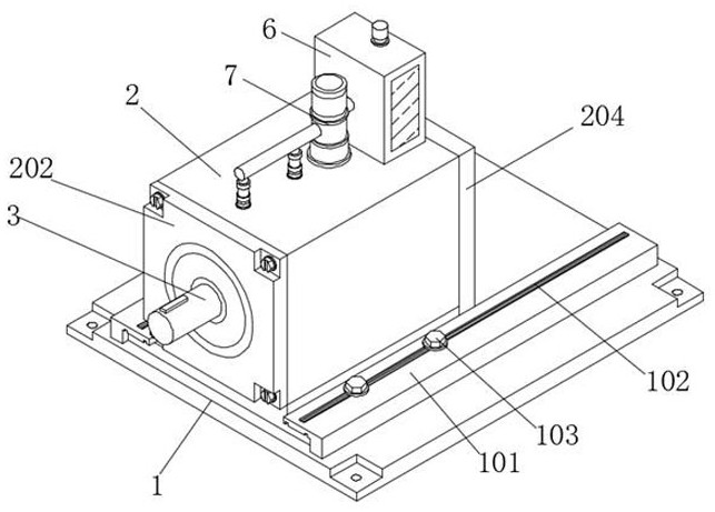
[0042] Embodiment 1, a planetary gear reduction box with self-controlled lubrication effect, including a base 1 and a casing 2, two sets of symmetrically arranged limiting clamps 101 are installed on the top of the base 1, and the two sets of limiting clamps 101 Fitted on the top of both sides of the support plate 206, the top inner wall of the limit clamp 101 and the limit clamp 207 are mutually fitted, and the top of the limit clamp 101 is provided with a through groove 102, and the through groove 102 Tightening screws 103 are installed on the inner thread, and the tightening screws 103 are connected to the inner side of the support plate 206 by threads. The top of the base 1 is movably equipped with a support plate 206, and the top of the support plate 206 is equipped with two groups of symmetrically distributed The limit clip 207 is used to fix the base 1 at a designated position through bolts, which is convenient for workers to fix the device. The worker fits the support p...

Embodiment 2

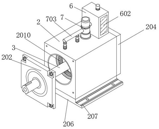
[0044] The second embodiment includes a base 1 and a shell 2, the top of which is equipped with a shell 2, and the shell 2 is located between two sets of limit clips 207, and a sound insulation layer 201 is installed inside the shell 2, and the shell 2 Two sets of inner gear rings 2010 are installed on the inner wall, and the inner gear rings 2010 are located in front of the controller 208. A controller 208 is installed on the top of the inner wall of the housing 2, and a sound sensor 209 is installed at the bottom of the controller 208. The gear rings 2010 in the group are respectively located in front of the corresponding two groups of oil delivery pipes 5, the support plate 206 fixes the top shell 2 to ensure the stability of the shell 2, the shell 2 is fixed to the inner sound insulation layer 201, and the sound insulation layer 201 is installed on the device The outer side of the gear, thereby reducing the transmission of noise, will produce sound in the process of mutual ...

Embodiment 3

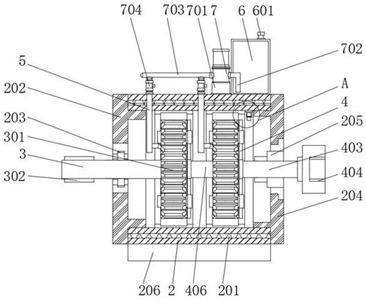
[0046] The third embodiment includes a base 1 and a housing 2, the front end of the housing 2 is equipped with a front closure cover 202 through bolts, the inside of the front closure cover 202 is equipped with a first bearing ring 203, and the inside of the first bearing ring 203 is movable An output transmission rod 3 is installed, the front end of the output transmission rod 3 is equipped with a transmission clip 302, the rear end of the output transmission rod 3 is equipped with a first sun gear 301, and the rear end of the housing 2 is installed with a Rear closing cover 204, the inner side of described rear closing cover 204 is installed with second bearing ring 205, and the inner side of described second bearing ring 205 is movably installed with rotating rod 403, and the front end of described rotating rod 403 is installed with first planet carrier 4. The rear end of the rotating rod 403 is equipped with a motor connection port 404, and the front of the first planet car...


PUM


Abstract

The planetary gear reduction gearbox with the autonomous lubrication control effect comprises a base and a shell, a supporting plate is movably installed at the top of the base, two sets of symmetrically-distributed limiting clamping strips are installed at the top of the supporting plate, the shell is installed at the top of the supporting plate, and the shell is located between the two sets of limiting clamping strips; and a front sealing cover is mounted at the front end of the shell through bolts. An oil delivery pump is installed, the oil delivery pump pumps lubricating oil in an oil storage tank through an oil pumping pipe, the lubricating oil enters an oil guide pipe, during oil delivery, a control valve is opened to enable the lubricating oil to smoothly enter an oil delivery pipe, and a lubricating oil dropper on the oil delivery pipe drips the oil on a first sun gear and a second sun gear; through meshing of the clamping teeth, lubricating oil can be distributed on the surface of each gear, friction force on the device is reduced, normal transmission of the device is facilitated, and meanwhile friction loss between the gears in the transmission process of the device is reduced.

Description

technical field [0001] The invention relates to the technical field of reduction boxes, in particular to a planetary gear reduction box with self-controlled lubricating effect. Background technique [0002] Planetary gear reducer is also called planetary reducer, servo reducer. In the reducer family, planetary reducers are widely used in servo motors, stepping motors, DC motors and other transmission systems due to their small size, high transmission efficiency, wide deceleration range, and high precision. Its function is to reduce the rotational speed, increase the torque and reduce the moment of inertia ratio of the load / motor under the premise of ensuring precision transmission. [0003] The defective that planetary gear reduction box exists in the prior art is: [0004] 1. The patent document CN213839452U discloses a planetary gear reducer, "the planetary gear reducer has an input shaft and three output shafts, the input shaft is connected to a motor, the motor drives ...

Claims


Application Information

Patent Timeline
Patent Type & Authority Applications(China)
IPC IPC(8): F16H57/04F16H57/028F16H57/023F16H57/025G01H17/00F16H1/36
CPCF16H57/0434F16H57/0421F16H57/0479F16H57/028F16H57/023F16H57/025G01H17/00F16H1/36Y02E10/72
Inventor 李巍
Owner 广东威强科技有限公司
Why Eureka
Try Eureka