PE water supply pipe

A technology for water supply pipes and hoses, applied in the field of pipe manufacturing, can solve the problems of physical power consumption, unfavorable use, small footprint, etc., and achieve the effects of physical strength saving, rapid laying, and reduction of impact pressure.

Pending Publication Date: 2022-05-20
宁波格鲁德科技有限公司
View PDF0 Cites 0 Cited by
  • Summary
  • Abstract
  • Description
  • Claims
  • Application Information

AI Technical Summary

Problems solved by technology

[0003] In the prior art, when a fire breaks out in a city, the firefighters drive the fire truck to put out the fire. When the fire truck arrives at the scene, the firefighters need to lay the fire pipes immediately. However, the existing fire pipes are usually composed of hoses. The hose is chosen as the first choice for fire extinguishing due to its excellent folding performance, which makes its footprint small and easy to carry. However, the hose will be rolled up when it is not in use, so that the hose is generally flat. Therefore, when using it, it is necessary to quickly unfold it to pass water to realize fire extinguishing and firefighting, and the time of firefighting is a very important indicator, so when the hose is unfolded, the firefighters will consume a lot of energy, which is not conducive to the follow-up At the same time, because the hose is too soft, it will inevitably fold together even if it is unfolded. This situation will make the hose bend at a right angle, and then seal the pipe, so the water pressure sprayed in an instant Under the action of the hose, the front end of the hose will swing, and the metal pipe connected to the front end of the hose will hit the rescuers, which is very unfavorable for use.

Method used


Image

  • PE water supply pipe
  • PE water supply pipe
  • PE water supply pipe

Examples


Embodiment Construction

[0018] use Figure 1-Figure 4 A PE water supply pipe according to an embodiment of the present invention is described as follows.

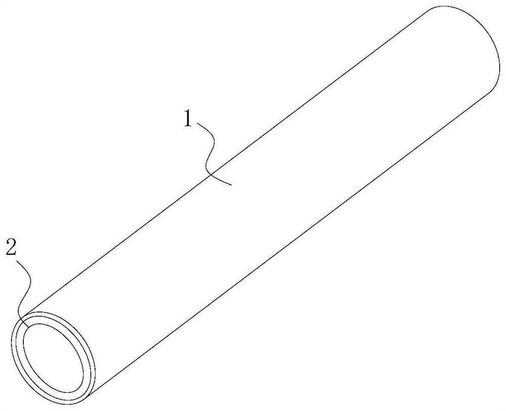
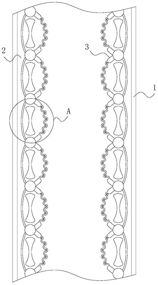
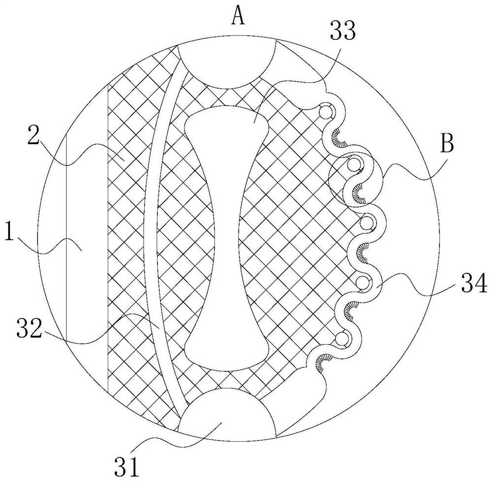
[0019] Such as Figure 1-Figure 4 As shown, a PE water supply pipe according to the present invention includes a main body 1, a PE pipe 2 and a protection mechanism 3; the main body 1 is composed of a normal hose, and the inner surface of the main body 1 is fixedly sleeved with a PE pipe 2, The main body 1 is stored in a winding roller; the inside of the PE pipe 2 is provided with a protection mechanism 3; the protection mechanism 3 includes a mounting ring 31, an elastic ring 32, a special-shaped groove 33, a corrugated ring 34, a vibration chamber 35 and Bristles 36; the mounting rings 31 are inlaid and fixedly installed in the wall of the PE pipe 2 at fixed intervals, and the mounting rings 31 are connected by elastic rings 32; the two ends of the elastic rings 32 are fixedly connected to the mounting rings 31 On the outer surface, the elasti...


PUM


Abstract

The invention belongs to the technical field of pipe manufacturing, and particularly relates to a PE water supply pipe which comprises a main body, a PE pipe and a protection mechanism. The main body is composed of a normal water hose, the inner surface of the main body is fixedly sleeved with a PE pipe, and the main body is stored in a winding roller mode; a protection mechanism is arranged in the PE pipe; the protection mechanism comprises a mounting ring, an elastic ring, a special-shaped groove, a corrugated ring, a vibration cavity and bristles; the mounting rings are embedded and fixedly mounted in the wall of the PE pipe at fixed intervals, and the mounting rings are connected through the elastic rings; when the PE pipe is released, the PE pipe cannot be folded like a water hose, so that high-pressure water flow which is going to pass next cannot be blocked, the PE pipe can only have a storage action through the design, the PE pipe can be automatically released by virtue of the elasticity of the PE pipe during release, the effect of quickly paving the PE pipe can be achieved, and the service life of the PE pipe is prolonged. And the physical strength of the firefighter can be saved to a certain degree, so that the following more important fire extinguishing task is facilitated.

Description

technical field [0001] The invention belongs to the technical field of pipe material manufacturing, in particular to a PE water supply pipe. Background technique [0002] Water supply pipes are divided into metal pipes, composite pipes and plastic pipes. Metal pipes are mainly divided into copper pipes and stainless steel water pipes. Metal pipes have many characteristics such as safety, sanitation, and durability. , has been gradually eliminated; the most commonly used plastic pipes are PPR water pipes, which are safe, non-toxic, easy to install, low in price and many other reasons, making them the most commonly used water pipes for home improvement. However, due to problems such as environmental hormones, more and more people are beginning to use metal pipes or ppr-lined metal pipes as water supply pipes; the performance indicators of water supply pipes are relatively strict, especially for drinking water, which requires pipes to have Non-toxic and radiation-free, no har...

Claims


Application Information

Patent Timeline
IPC IPC(8): F16L57/02F16L9/12F16L55/027
CPCF16L57/02F16L9/12F16L55/02736
Inventor 黄家怀
Owner 宁波格鲁德科技有限公司
Why Eureka
Try Eureka