Physical mechanics demonstration device

A demonstration device and mechanics technology, applied in the field of education, can solve the problems of inability to adjust the height, low practicability, inconvenient movement, etc., and achieve the effect of reducing work fatigue, avoiding manual handling, and improving portability

Inactive Publication Date: 2022-05-20
黄灵万
View PDF0 Cites 2 Cited by
  • Summary
  • Abstract
  • Description
  • Claims
  • Application Information

AI Technical Summary

Problems solved by technology

[0004] In view of the above situation, in order to overcome the defects of the prior art, the present invention provides a physical and mechanical demonstration device, which effectively solves the problem that the existing physical and mechanical demonstration device in the above background technology is inconvenient to move, resulting in poor portability and fixed height. , the height cannot be adjusted according to operators of different heights, resulting in the problem of low practicality

Method used


Image

  • Physical mechanics demonstration device
  • Physical mechanics demonstration device
  • Physical mechanics demonstration device

Examples


Embodiment 1

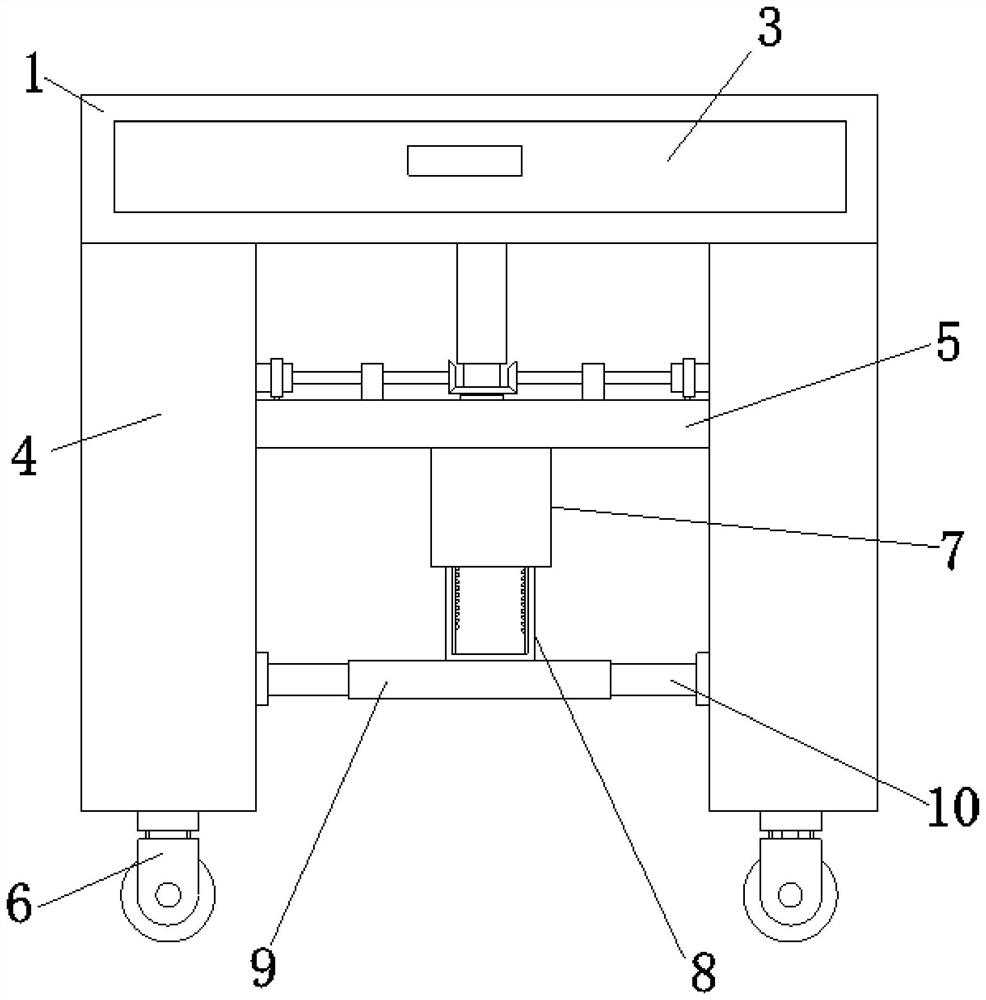
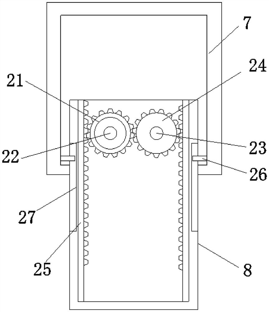
[0033] Embodiment one, by Figure 1 to Figure 7 Given, the present invention comprises demonstration console 1, and the inside of demonstration console 1 is provided with storage tank 2, and the inside of storage tank 2 is interspersed with storage cabinet 3, through the design of storage cabinet 3, it is convenient to store mechanics demonstration tool, and then improved For the storage performance of the device, support columns 4 are symmetrically arranged on both sides of the bottom end of the demonstration console 1, two adjacent support columns 4 are connected by support plates 5, and two support columns 4 are symmetrically arranged at the bottom ends of the two support columns 4. Universal wheel 6, the bottom end of support plate 5 is provided with installation box 7, and the bottom of installation box 7 is provided with elevating rod 8, and elevating rod 8 is U-shaped structure, and the inside of installation box 7 is provided with the promotion that is connected with el...

Embodiment 2

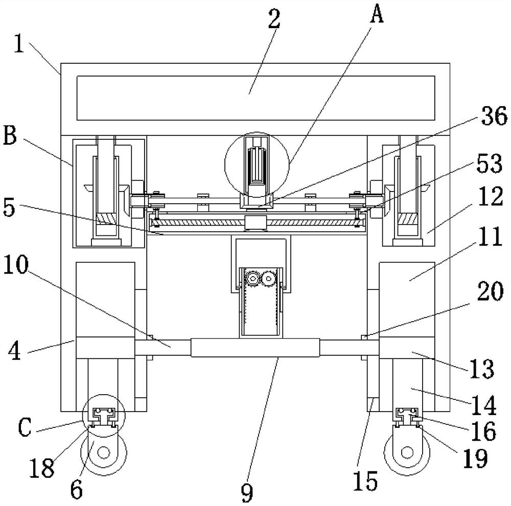
[0036] Embodiment two, on the basis of embodiment one, by figure 1 , figure 2 and Figure 7 Given, the inner bottom end of the installation box 7 is symmetrically provided with a block 26, and the outer wall of the elevating rod 8 is provided with a slot 27 which is slidably connected with the block 26. Rod 16 and connecting groove 17, two support columns 4 close to each other are all symmetrically provided with the chute 15 that communicates with accommodating groove one 11, and the interior of accommodating groove one 11 is provided with slide plate 13, and one end of slide bar 10 runs through The chute 15 is connected to the side wall of the slide plate 13, the bottom end of the slide plate 13 is provided with a push rod 14, and the bottom end of the push rod 14 is provided with an engaging groove 17, and the top end of the universal wheel 6 is provided with an engaging rod located inside the engaging groove 17 16. The cross-sections of the connecting rod 16 and the conn...

Embodiment 3

[0038] Embodiment three, on the basis of embodiment one, by Fig. figure 2 and Figure 4 Given, the height adjustment mechanism includes a driving group, a transmission group, an adjusting group and a lifting group, and the driving group includes a sleeve 28, a mounting cylinder 29, a lifting cylinder 30, a motor 2 31, a rotating shaft 32, a connecting block 33, and a limit groove 34 , limit block 35 and bevel gear one 36, the middle position of the bottom end of demonstration console 1 is provided with sleeve 28, the inside of sleeve 28 is interspersed with the installation cylinder 29 that is connected with support plate 5, and the bottom end of installation cylinder 29 The bevel gear 1 36 is sleeved, the inside of the installation tube 29 is interspersed with a lifting tube 30, the inner top of the sleeve 28 is provided with a motor 2 31, the output shaft of the motor 2 31 is connected with a rotating shaft 32, and the bottom of the rotating shaft 32 The connecting block 3...


PUM


Abstract

The invention relates to the technical field of education, and discloses a physical mechanics demonstration device which solves the problems that an existing physical mechanics demonstration device is inconvenient to move, so that the portability is poor, meanwhile, the height is fixed, the height cannot be adjusted according to operators with different heights, and the practicability is not high. A containing groove is formed in the demonstration operation table, a containing cabinet is inserted into the containing groove in a penetrating mode, supporting columns are symmetrically arranged on the two sides of the bottom end of the demonstration operation table, every two adjacent supporting columns are connected through a supporting plate, two universal wheels are symmetrically arranged at the bottom end of each supporting column, and a mounting box is arranged at the bottom end of each supporting plate. A lifting rod is arranged below the mounting box and is of a U-shaped structure; through the design of the height adjusting mechanism, the height of the demonstration operation table can be conveniently adjusted according to the height of an operator, the operator can conveniently carry out force demonstration work, and meanwhile the work fatigue degree of the operator is reduced.

Description

technical field [0001] The invention belongs to the field of education technology, in particular to a physical mechanics demonstration device. Background technique [0002] The knowledge of energy conversion is described in physics textbooks. An elevated object has potential energy, and a moving object has kinetic energy. They can be transformed into each other, and energy can be converted from one form of energy to another form of energy. [0003] However, the existing physical mechanics demonstration device is inconvenient to move, resulting in poor portability, and at the same time, the height is fixed, and the height cannot be adjusted according to operators of different heights, resulting in low practicability. Contents of the invention [0004] In view of the above situation, in order to overcome the defects of the prior art, the present invention provides a physical and mechanical demonstration device, which effectively solves the problem that the existing physical ...

Claims


Application Information

Patent Timeline
Patent Type & Authority Applications(China)
IPC IPC(8): G09B23/08
CPCG09B23/08
Inventor 黄灵万邓德坚杨年斌廖丰政蒙荣珍潘春梅张港生罗正强温巧蓝善斌莫奋德杨小明邓江兴
Owner 黄灵万
Why Eureka
Try Eureka