Eureka AIR delivers breakthrough ideas for toughest innovation challenges, trusted by R&D personnel around the world.

Vacuum chamber and wafer machine

A vacuum chamber and wafer technology, which is applied in semiconductor/solid-state device testing/measurement, electrical components, circuits, etc., can solve the problems of reducing the production capacity of wafer machines, wasting time for restarting machines, and easy wear of rubber rings, etc., to achieve Eliminate manual correction of downtime, reduce waste, and increase productivity

Pending Publication Date: 2022-05-20
CHANGXIN MEMORY TECH INC
View PDF0 Cites 0 Cited by
  • Summary
  • Abstract
  • Description
  • Claims
  • Application Information

AI Technical Summary

Problems solved by technology

Due to the poor discharge of the electrostatic chuck in the cavity of the vacuum chamber and the easy wear and tear of the rubber ring on the robot arm, the position of the wafer is prone to shift during the process of transferring in or out, resulting in the need to stop the vacuum chamber to correct the wafer. The position of the circle, which will lead to waste of re-machine time, reduce the productivity of the wafer machine, and easily cause wafer defects

Method used


Image

  • Vacuum chamber and wafer machine
  • Vacuum chamber and wafer machine
  • Vacuum chamber and wafer machine

Examples


Embodiment Construction

[0039] Typical embodiments embodying the features and advantages of the present invention will be described in detail in the following description. It should be understood that the present invention can have various changes in different embodiments without departing from the scope of the present invention, and that the description and drawings therein are illustrative in nature and not intended to limit the present invention. invention.

[0040] In the following description of various exemplary embodiments of the invention, reference is made to the accompanying drawings, which form a part hereof, and in which are shown by way of example different exemplary structures, systems, and embodiments in which aspects of the invention may be implemented and steps. It is to be understood that other specific arrangements of components, structures, exemplary devices, systems and steps may be utilized and structural and functional modifications may be made without departing from the scope...


PUM

PropertyMeasurementUnit
Thicknessaaaaaaaaaa
Radiusaaaaaaaaaa

Abstract

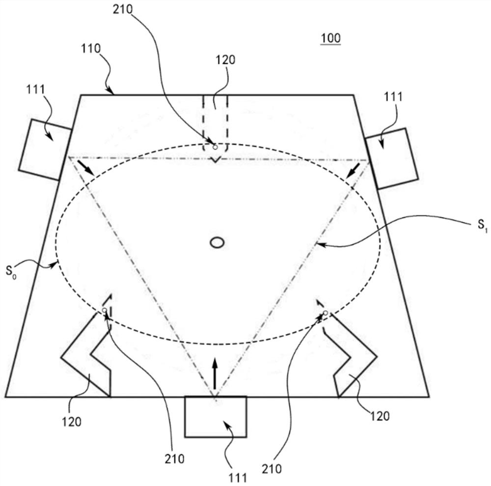
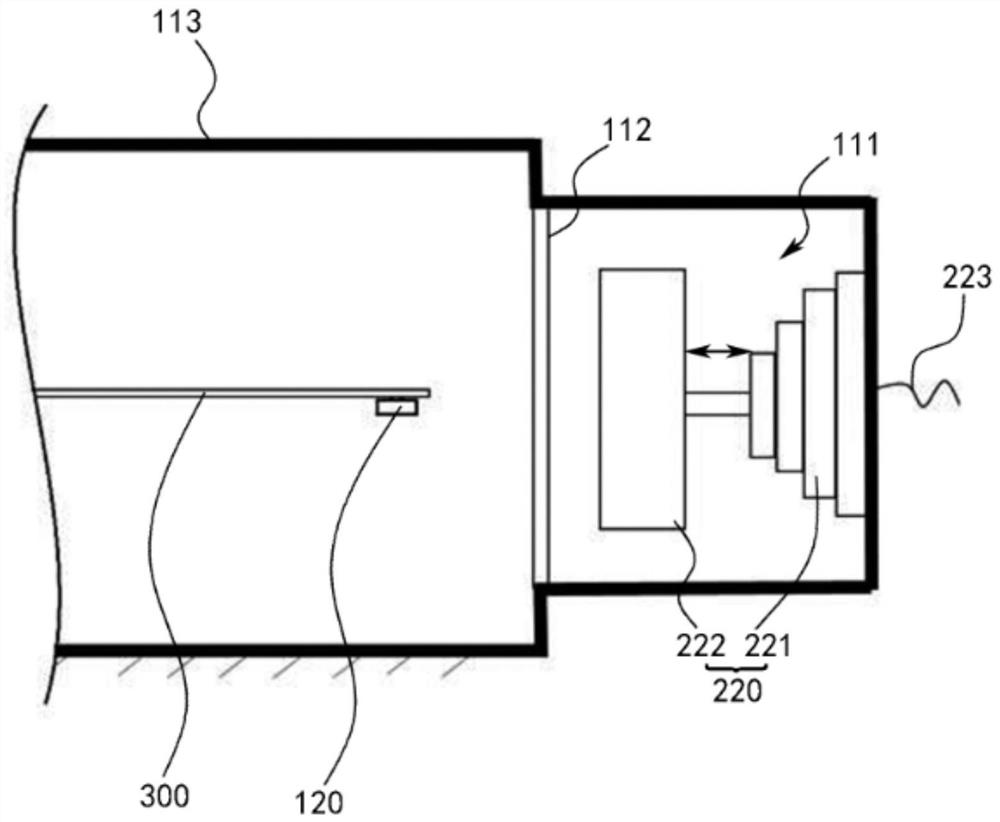
The invention provides a vacuum chamber and a wafer machine table. Supporting legs used for bearing a wafer are arranged in the vacuum chamber. The vacuum chamber further comprises a wafer position correction system, and the wafer position correction system comprises a sensing unit, an adjusting unit and a control system. The sensing units are arranged on the supporting legs and used for sensing pressure signals applied by the wafer on the upper portion, and the sensing units are distributed on the edge of a calibration area; the adjusting units are distributed in the vacuum chamber around the periphery of the calibration area and are used for adjustably pushing the wafer; the control system is electrically connected to the sensing unit and the adjusting unit and used for selecting and controlling part of the adjusting unit to adjust the position of the wafer according to the pressure signal so that the center of the wafer can coincide with the center of the calibration area.

Description

technical field [0001] The invention relates to the technical field of semiconductor manufacturing, in particular to a vacuum chamber and a wafer machine. Background technique [0002] In the wafer machine, the vacuum chamber (AirLock) is a device for switching between vacuum and atmosphere. Due to the poor discharge of the electrostatic chuck in the cavity of the vacuum chamber and the easy wear and tear of the rubber ring on the robot arm, the position of the wafer is prone to shift during the process of transferring in or out, resulting in the need to stop the vacuum chamber to correct the wafer. The position of the circle will lead to a waste of re-machine time, reduce the productivity of the wafer machine, and easily cause wafer defects. Contents of the invention [0003] A main purpose of the present invention is to overcome at least one defect of the above-mentioned prior art, and provide a vacuum chamber capable of correcting the position of the wafer without stop...

Claims


Application Information

Patent Timeline
IPC IPC(8): H01L21/68H01L21/67
CPCH01L21/68H01L21/67069H01L21/67H01L22/00
Inventor 汪铮铮刘凯
Owner CHANGXIN MEMORY TECH INC
Why Eureka
Eureka Blog
Learn More