Communication antenna radiator structure made of conductive polymer material
A conductive polymer and communication antenna technology, applied in the field of communication antennas, can solve the problems of large windward area of antenna radiators, poor response to bad weather, and influence on communication transmission effects, etc., to achieve high protection performance, guarantee protection effects, and improve communication The effect of the transfer effect
- Summary
- Abstract
- Description
- Claims
- Application Information
AI Technical Summary
Problems solved by technology
Method used
Image
Examples
Embodiment 1
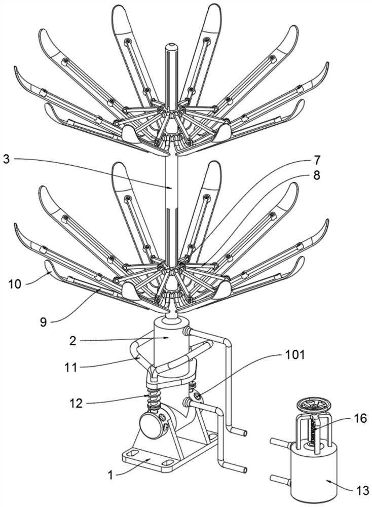
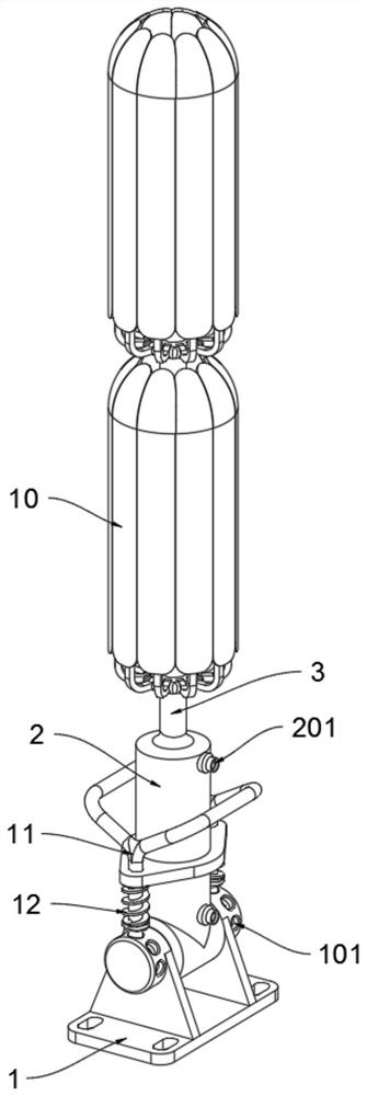
[0039] as attached figure 1 to attach Figure 10 Shown:
[0040] The present invention provides a communication antenna radiator structure made of conductive polymer materials, including a base 1, a locking pin 11 and a hydraulic part 13;
[0041] The top of the base 1 is connected to the support bottom column 2, and the inside of the support bottom column 2 is hollow, and the top of the support bottom column 2 is connected with a support rod 3; the support rod 3 is connected with two movable parts 7, and the movable parts 7 pass through the connecting The rod 8 is connected with the antenna support rod 9; the outside of the support rod 3 is surrounded by two sets of antenna support rods 9, the bottom end of the antenna support rod 9 is connected with the support rod 3 in rotation, and the antenna board 10 is fixedly installed on the outside of the antenna support rod 9 , the antenna board 10 is arc-shaped, the two sides of the antenna board 10 are in contact with the adjace...
Embodiment 2
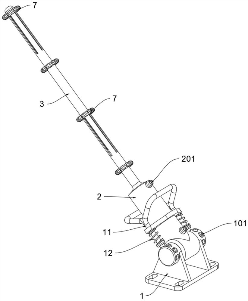
[0045] The bottom end of the support base 2 is rotatably connected to the inside of the base 1, and the left and right ends of the base 1 are provided with five limit grooves 101 in a semicircular shape, and the outer left and right ends of the support base 2 are slidingly connected with locking pins 11 to lock The two ends of the bottom of the pin 11 are slidably inserted into the limit grooves 101 at the left and right ends of the base 1, and the outer sides of the two ends of the bottom of the locking pin 11 are respectively fitted with springs 12, and the top of the spring 12 is attached to the bottom side of the supporting bottom column 2;
[0046] Using the above-mentioned technical solution, according to the needs of communication transmission, the support bottom column 2 on the top of the base 1 is rotated and adjusted, thereby changing the angle of the support rod 3, and after the support bottom column 2 is rotated and adjusted, the two ends of the bottom of the locking...
Embodiment 3
[0048] The interior of the hydraulic part 13 is hollow, and the upper and lower ends of the outer side of the hydraulic part 13 are respectively provided with liquid holes B1302. The liquid holes B1302 are connected to the liquid hole A201 through a hose, and the active piston rod 14 is slidably connected to the inside of the hydraulic part 13. The bottom of the active piston rod 14 is fixed with an active piston plate 15, the periphery of the active piston plate 15 is slidingly connected with the inside of the hydraulic part 13, the top of the hydraulic part 13 is provided with a screw hole 1301, and the screw rod 16 is threaded in the screw hole 1301, and the screw rod 16 The bottom end is rotatably connected to the top of the active piston rod 14;
[0049] With the above technical scheme, when the screw rod 16 drives the active piston plate 15 at the bottom of the active piston rod 14 to move downward, the active piston plate 15 presses the hydraulic oil at the bottom of the...
PUM
 Abstract
Description
Claims
Application Information
 - R&D
- Intellectual Property
- Life Sciences
- Materials
- Tech Scout
- Unparalleled Data Quality
- Higher Quality Content
- 60% Fewer Hallucinations
Browse by: Latest US Patents, China's latest patents, Technical Efficacy Thesaurus, Application Domain, Technology Topic, Popular Technical Reports.
© 2025 PatSnap. All rights reserved.Legal|Privacy policy|Modern Slavery Act Transparency Statement|Sitemap|About US| Contact US: help@patsnap.com


