Brush wire winding device for heavy grinding brush machining

A technology of winding device and brush wire, applied in the direction of brushes, bristles, applications, etc., can solve the problems of low efficiency and labor consumption, and achieve the effect of improving efficiency, high degree of automation, and reasonable design

Inactive Publication Date: 2022-05-24
安徽省潜山县团结制刷有限公司
View PDF0 Cites 0 Cited by
  • Summary
  • Abstract
  • Description
  • Claims
  • Application Information

AI Technical Summary

Problems solved by technology

[0004] The purpose of the present invention is to solve the problems of labor-intensive and low efficiency in the prior art, and propose a brush filament winding device for heavy grinding and brushing processing

Method used


Image

  • Brush wire winding device for heavy grinding brush machining
  • Brush wire winding device for heavy grinding brush machining
  • Brush wire winding device for heavy grinding brush machining

Examples


Embodiment 1

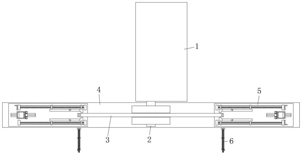
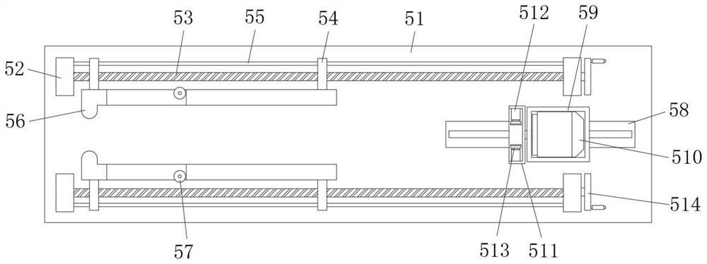
[0028] Reference Figure 1-5, a kind of brush wire winding device for heavy brush processing, including servo drive box 1, servo drive box 1 output end fixed with a rotating rod 2, rotating rod 2 outer wall fixed with a brush disc 3, servo drive box 1 front side is provided with a workbench 4, table 4 top surface is installed on both sides of the winding mechanism 5, winding mechanism 5 includes mount 51, mount 51 sliding damping is connected to the top surface of the workbench 4, mount 51 top surface is fixed to the support 52, the front and rear sides of the two supports 52 are rotated between the two sides of the connection with a threaded rod 53, Threaded rod 53 outer wall is connected by thread to the mounting sleeve 54, the front and rear mounting sleeve 54 also slides to connect the fin rod 55, and both sides of the limit rod 55 are fixed to the 52 side walls of the support, the front and rear side mounting set 54 is close to the mounting seat 51 The center side is fixed wit...

Embodiment 2

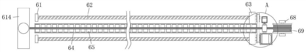
[0030] as Figure 1 、 3And 4 shown, the present embodiment and Example 1 is substantially the same, preferably, the wire feeding mechanism 6 includes a support seat 61, the same side of the two support seats 61 are rotated between the connection to the screw 62, the two screw 62 front ends are extended to the support seat one 61 outside and rotated connected to the conveyor belt, the two screw 62 outer wall is connected by thread 63, the advance plate 63 top surface is fixed with a wire feeding frame 64, the inner wall of the wire feeding frame 64 is also rotated and connected to the conveyor roller 65, and the front side of the pole 61 is also provided with an installation box two 66 , the inner wall of the installation box two 66 is fixed with a servo motor two 67 through screws, the servo motor two 67 output end is fixed with one of the screw 62, the support seat one 61 is also provided on both sides of the front end of the fixed seat 68, the fixed seat 68 is rotated and connect...

Embodiment 3

[0033] as Figure 3 and 5 As shown, the present embodiment and Example 1 are substantially the same, preferably, the slitting component 614 includes a mounting bracket 6141, the outer top surface of the mounting frame 6141 is screwed with a cylinder 6142, the output of the cylinder 6142 is fastened by a screw with a slitting knife 6143, and the inner wall of the mounting frame 6141 is also fixed with a plate 6144.

[0034] In the present embodiment, after the completion of the feeding, the cylinder 6142 drives the slitting knife 6143 down to achieve rapid slitting of the brush wire, thereby realizing the continuous conveying operation of the brush wire.


PUM


Abstract

The brush wire winding device comprises a servo driving box, a rotating rod is fixed to the output end of the servo driving box, a brush disc is fixed to the outer wall of the rotating rod, a workbench is arranged on the front side of the servo driving box, winding mechanisms are installed on the two sides of the top face of the workbench, and each winding mechanism comprises an installation base; the mounting base is slidably connected to the top face of the workbench in a damping mode, supports are fixed to the four corners of the top face of the mounting base, threaded rods are rotatably connected between the supports on the front side and the rear side, mounting sleeves are connected to the outer walls of the threaded rods through threads, and limiting rods are slidably connected to the inner sides of the mounting sleeves at the front end and the rear end; the two sides of the limiting rod are fixed to the side wall of the support. The device is reasonable in design, stable in device operation and high in automation degree, so that the machining efficiency of the heavy grinding brush is greatly improved, and a certain guarantee is provided for batch rapid production of the heavy grinding brush.

Description

Technical field [0001] The present invention relates to the technical field of re-research brush production equipment, in particular to a re-research brush processing with a brush wire winding device. Background [0002] Heavy research brush is a kind of for different uses to select the corresponding type of steel wire, select different wire diameter brush, steel wire has straight wire and corrugated wire two, the thickness of the wire can be determined according to different needs, straight wire and curved wire two, straight wire suitable for drilling holes and hair planting brush more brushes, such as wood plate steel wire brush, wooden handle steel wire brush, disc wire brush, etc., in the preparation of disc steel wire brush need to be banded and wound, which requires the use of winding wire equipment. [0003] The existing winding wire automation is low, the feeding is inconvenient, and multiple processes require manual assistance during bundling, which seriously affects the...

Claims


Application Information

Patent Timeline
Patent Type & Authority Applications(China)
IPC IPC(8): A46D1/04A46D1/06
CPCA46D1/04A46D1/06Y02P70/10
Inventor 徐团结华月年徐仪琼
Owner 安徽省潜山县团结制刷有限公司
Why Eureka
Try Eureka