
Automobile control accessory assembling production line

A technology for automobile control and control accessories, applied in the direction of assembly machine, comprehensive factory control, manufacturing tools, etc., can solve problems such as automatic assembly of control accessories that are not realized, achieve continuous supply and automatic assembly, reasonable and compact layout, and meet continuous sexual effect

Pending Publication Date: 2022-05-24
浙江金麦特智能装备有限公司
View PDF13 Cites 0 Cited by
  • Summary
  • Abstract
  • Description
  • Claims
  • Application Information

AI Technical Summary

Problems solved by technology

[0005] However, in the existing technical solutions, it involves the assembly of steering wheel units, springs, bearings, clocks and shields, etc., but does not realize the automatic assembly of specific control accessories.

Method used


Image

  • Automobile control accessory assembling production line
  • Automobile control accessory assembling production line
  • Automobile control accessory assembling production line

Examples


Embodiment 1

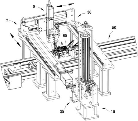
[0050] like figure 1 As shown, the automobile control parts assembly production line includes: a continuous feeding module 10, the continuous feeding module 10 is configured as a rotary multi-material tube structure, and according to the feeding progress, the continuous feeding module 10 rotates step by step, so that the Each feeding pipe works in sequence for continuous feeding; a transition feeding module 20, the transition feeding module 20 is docked with the discharge end of the transition feeding module 20; and a feeding module 30, the feeding module 30 is connected to the The transitional feeding module 20 is arranged in coordination; the control accessories 40 are continuously output and supplied by the continuous feeding module 10 , and are received and inspected by the transitional feeding module 20 one by one, and then transferred and assembled by the feeding module 30 .

[0051] Preferably, as figure 1 As shown, it also includes: an assembly conveying line 50 , the...

Embodiment 2

[0065] The same or corresponding components in this embodiment and the above-mentioned embodiments are marked with corresponding reference numerals as in the above-mentioned embodiments. For the sake of simplicity, only the points of difference from the above-mentioned embodiments will be described below. The difference between this embodiment and the above-mentioned embodiment is:

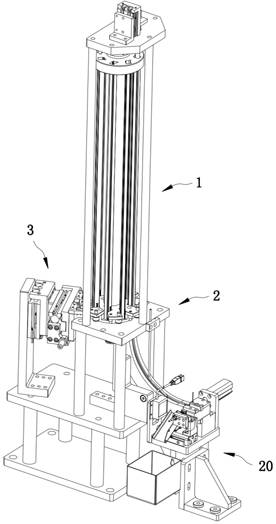
[0066] Preferably, as Figure 5 As shown, the rotary feeding mechanism 1 further includes: an auxiliary positioning structure 14, the auxiliary positioning structure 14 is cooperatively arranged between the bottom of the rotary feeding frame 12 and the feeding frame 2, which is assisted by a fixed-point engaging action The rotating material rack 12 is rotated in place step by step.

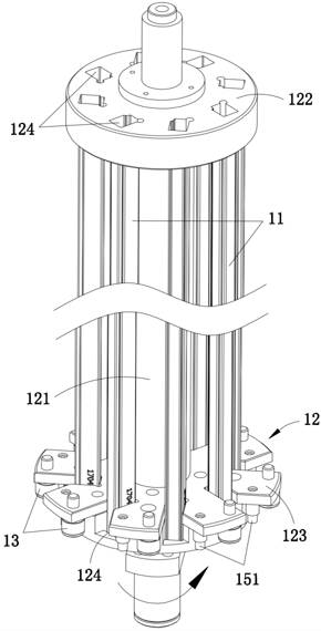
[0067] Preferably, as Figure 13 As shown, the auxiliary positioning structure 14 includes: elastic ball structures 141 arranged in a circular array at the bottom of the rotating material rack 12, and a plurality of...

Embodiment 3

[0072] The same or corresponding components in this embodiment and the above-mentioned embodiments are marked with corresponding reference numerals as in the above-mentioned embodiments. For the sake of brevity, only the points of difference from the above-mentioned embodiments are described below. The difference between this embodiment and the above-mentioned embodiment is:

[0073] Preferably, as Figure 8 As shown, the transition feeding module 20 includes: a feeding mechanism 5, such as Figure 9-10 As shown, the material receiving mechanism 5 includes: a material receiving seat 51, and the material receiving seat 51 is slidably arranged on the feeding frame 52 so as to be connected to or staggered from the discharge end of the continuous feeding module 10; and the clamping drive part 53, the material receiving seat 51 is connected with the translation driving end of the clamping driving part 53, after the receiving seat 51 is connected to a control accessory 40, the clampi...


PUM


Abstract

According to the automobile control part assembling production line, the feeding module, the feeding module and the conveying module are arranged on the conveying path of the assembling conveying line for continuously conveying automobile parts in a matched mode, the continuous feeding module is arranged to be of a rotary type multi-material-pipe structure, stepping shifting switching of material pipes can be automatically conducted according to the feeding progress, and therefore the production efficiency is improved. The feeding module is used for feeding the control accessories to be matched and butted with the lower feeding channel and continuously supplying the control accessories to the transition feeding module, and matched with one-by-one detection feeding of the transition feeding module, the feeding module transfers the qualified control accessories in a matched mode and installs the control accessories on the automobile accessories, and continuous supply and automatic assembly of the control accessories are achieved. According to the automatic feeding device, the continuity and accuracy of automatic feeding can be fully met, all modules are reasonable and compact in layout arrangement, the automatic assembling efficiency is high, and the technical problems existing in the prior art are solved.

Description

technical field [0001] The invention relates to the technical field of automatic assembly of automobile control parts, in particular to an assembly production line of automobile control parts. Background technique [0002] At present, the on-off control mechanism of automobile combination switches on the market is generally mechanical. By turning the handle or knob, the moving contact piece is indirectly driven to move, and the static contact piece is connected and disconnected to realize the control function of the switch. In the assembly process of auto parts such as steering wheel, one of the steps is to match and install the control parts with the above functions. [0003] Chinese patent CN201420554044.4 discloses a control switching structure used in an automobile combination switch, including a static contact piece, a gland, a handle shaft, a slider and a gold finger contact piece, the static contact piece is arranged on the pressure cover, the slider is arranged betw...

Claims


Application Information

Patent Timeline
Patent Type & Authority Applications(China)
IPC IPC(8): B23P21/00
CPCB23P21/00Y02P90/02
Inventor 王辰晨施丽叶
Owner 浙江金麦特智能装备有限公司
Learn More