
Design method of heat dissipation device, heat dissipation device and manufacturing method of heat dissipation device

A technology of heat dissipation device and design method, which is applied in the design of heat dissipation device, the manufacture of heat dissipation device and heat dissipation device, which can solve the problems of burning out chips, reducing the operation speed of chips, and overheating of chips, so as to avoid the effect of overheating of chips

Pending Publication Date: 2022-05-24
北京微焓科技有限公司
View PDF0 Cites 0 Cited by
  • Summary
  • Abstract
  • Description
  • Claims
  • Application Information

AI Technical Summary

Problems solved by technology

[0003] The purpose of this application is to provide a design method of a heat sink, a heat sink and a manufacturing method of a heat sink, so as to solve the unsatisfactory heat dissipation effect of the current heat sink in the prior art on chips with high power consumption to a certain extent , The high power consumption chip works at a high temperature for a long time, which can easily lead to technical problems such as chip overheating, chip operation speed reduction, and even chip burnout.

Method used


Image

  • Design method of heat dissipation device, heat dissipation device and manufacturing method of heat dissipation device
  • Design method of heat dissipation device, heat dissipation device and manufacturing method of heat dissipation device
  • Design method of heat dissipation device, heat dissipation device and manufacturing method of heat dissipation device

Examples


Embodiment Construction

[0059] The technical solutions of the present application will be clearly and completely described below with reference to the accompanying drawings. Obviously, the described embodiments are part of the embodiments of the present application, but not all of the embodiments.

[0060] The components of the embodiments of the present application generally described and shown in the drawings herein may be arranged and designed in a variety of different configurations. Thus, the following detailed description of the embodiments of the application provided in the accompanying drawings is not intended to limit the scope of the application as claimed, but is merely representative of selected embodiments of the application.

[0061] Based on the embodiments in the present application, all other embodiments obtained by those of ordinary skill in the art without creative efforts shall fall within the protection scope of the present application.

[0062] In the description of this applica...


PUM


Abstract

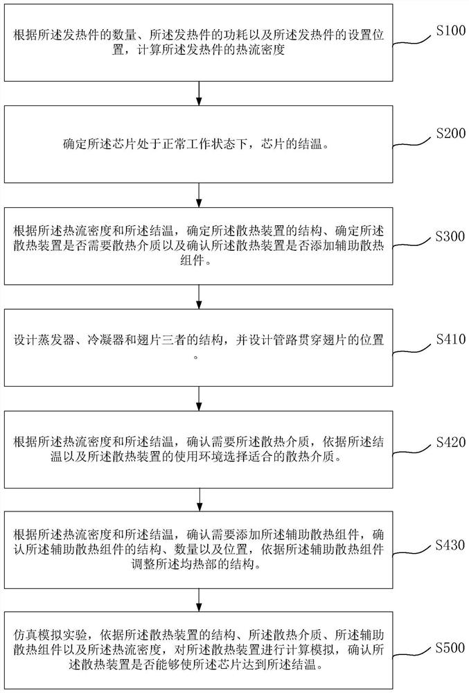
The invention relates to the technical field of heat dissipation equipment, in particular to a design method of a heat dissipation device, the heat dissipation device and a manufacturing method of the heat dissipation device.The design method of the heat dissipation device comprises the steps that the heat flux density of chips is calculated according to the number of the chips, the power consumption of the chips and the setting positions of the chips; determining the junction temperature of the chip when the chip is in a normal working state; and according to the heat flux density and the junction temperature, determining the structure of the heat dissipation device, determining whether the heat dissipation device needs a heat dissipation medium, and determining whether the heat dissipation device is added with an auxiliary heat dissipation assembly. According to the design method of the heat dissipation device, the heat dissipation device and the manufacturing method of the heat dissipation device, the heat flux density of the chip and the junction temperature of the chip are calculated through the power consumption of the chip, the heat dissipation capability of the heat dissipation device for normal operation of the chip is accurately determined, the heat dissipation device can enable the chip to work at the normal working temperature, and the heat dissipation efficiency of the heat dissipation device is improved. And the phenomena of chip overtemperature, chip operation speed reduction and even chip burnout are effectively avoided.

Description

technical field [0001] The present application relates to the technical field of heat dissipation equipment, and in particular, to a design method of a heat dissipation device, a heat dissipation device and a manufacturing method of the heat dissipation device. Background technique [0002] In order to meet consumers' pursuit of electronic product performance, the computing speed of electronic product chips is continuously improved. The higher the computing speed of the chip, the higher the power consumption of the chip. Correspondingly, the high power consumption of the chip (high power consumption can mean that the power consumption of the chip is greater than or equal to 800W) causes the chip to generate a great deal of heat during the operation of the chip. However, the heat dissipation effect of current heat sinks on high-power chips is not ideal. High-power chips work at high temperatures for a long time, which can easily lead to chip overheating, reduced chip computi...

Claims


Application Information

Patent Timeline
IPC IPC(8): G06F1/20G06F30/20H01L21/48H01L23/427H01L23/467G06F119/08
CPCG06F1/206G06F30/20H01L23/427H01L23/467H01L21/4882G06F2119/08Y02D10/00
Inventor 张晓林张晓屿尹航冉方圆连红奎孙萌田巍王娜李亚丽
Owner 北京微焓科技有限公司
Learn More