Gall-stone taking-out device for hepatobiliary surgery department

A technology for taking out devices and gallstones, which is applied in medical science, surgery, etc., can solve problems such as unsatisfactory results of stone removal, inconvenient removal of stones, and increased pain for patients, so as to reduce postoperative complications, shorten anesthesia time, and reduce surgical costs. risk effect

Pending Publication Date: 2022-05-27
张瑞昕
View PDF1 Cites 0 Cited by
  • Summary
  • Abstract
  • Description
  • Claims
  • Application Information

AI Technical Summary

Problems solved by technology

[0005] The above-mentioned stone removal device often causes the stones to slip due to insufficient friction w

Method used


Image

  • Gall-stone taking-out device for hepatobiliary surgery department
  • Gall-stone taking-out device for hepatobiliary surgery department
  • Gall-stone taking-out device for hepatobiliary surgery department

Examples


Embodiment 1

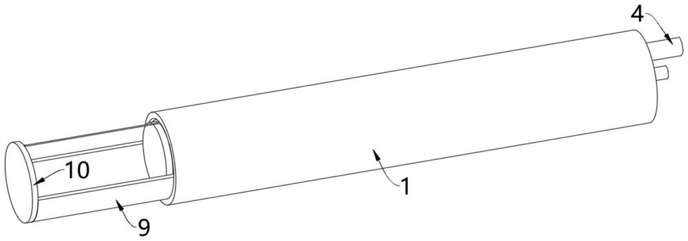
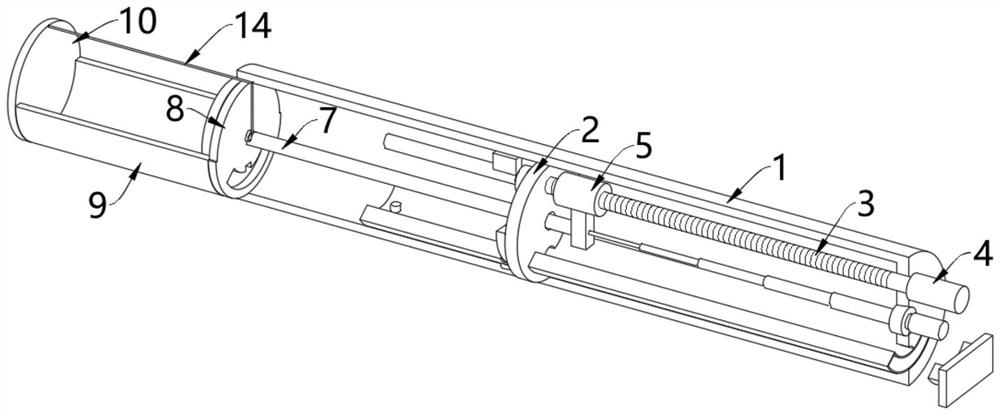
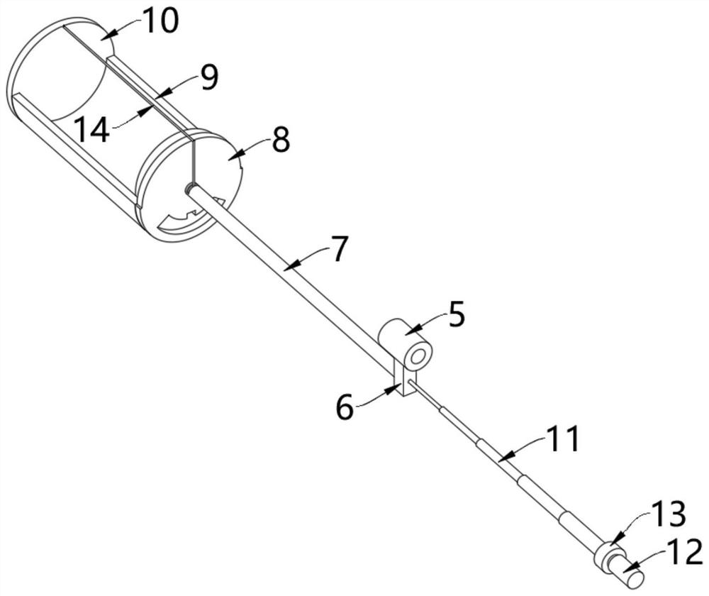
[0042] see Figure 1-Figure 5 , a gallstone extraction device for hepatobiliary surgery, comprising an outer cylinder 1, the middle part of the inner wall of the outer cylinder 1 is fixedly installed with a partition 2, the right side of the partition 2 is rotated and provided with a screw rod 3, and the right end of the screw rod 3 extends to the outside A knob 4 is fixedly connected to the outside of the cylinder 1, and the rotation of the screw rod 3 can be directly controlled by the knob 4. A screw nut 5 is threadedly connected to the outer wall of the screw rod 3, and a push block 6 is fixedly installed on the outer wall of the screw nut 5. The push block 6. A push rod 7 is fixedly installed on the side facing the partition plate 2. The left end of the push rod 7 passes through the partition plate 2 and is fixedly connected with the right side plate 8. The left side of the right side plate 8 is fixedly installed with a collection cylinder 9. The collection cylinder The le...

Embodiment 2

[0051] see Figure 6-Figure 9 , on the basis of the first embodiment, the inner top wall of the outer cylinder 1 is fixedly installed with the upper fixing block 17, the bottom of the upper fixing block 17 is fixedly installed with the insertion rod 18, and the inner bottom wall of the outer cylinder 1 is fixedly installed with the lower fixing block 19. The top of the lower fixing block 19 is fixedly installed with a storage cylinder 20, and the top of the left end of the storage cylinder 20 is fixedly installed with a limit rod 21, the position of the insertion rod 18 is fixed by the upper fixing block 17, and the storage cylinder is fixed by the lower fixing block 19. 20, the storage bin 20 is hollow and the two ends are connected;

[0052] like Figure 7 As shown, the upper half of the right side plate 8 is provided with a slot 22 coupled with the insertion rod 18, and the lower half of the right side plate 8 is provided with a cylinder groove 23 coupled with the storage ...


PUM


Abstract

The invention relates to the technical field of hepatobiliary surgery, and discloses a hepatobiliary surgery gall-stone extraction device which comprises an outer cylinder, a partition plate is fixedly mounted in the middle of the inner wall of the outer cylinder, a lead screw is rotatably arranged on the right side of the partition plate, a nut is in threaded connection with the outer wall of the lead screw, and a push block is fixedly mounted on the outer wall of the nut. A push rod is fixedly installed on the side, facing the partition plate, of the push block, and the left end of the push rod penetrates through the partition plate and is fixedly connected with a right side plate. During use, the end, provided with the collecting barrel, of the outer barrel extends into the body of a patient through a minimally invasive wound, then the rotary knob is screwed to enable the lead screw to rotate, the lead screw rotates to drive the nut in threaded connection with the outer wall of the lead screw to move left and right, and the nut moves left and right to drive the push rod to move left and right through the push block; and the right side plate, the collecting barrel and the left side plate can be pushed out of the outer barrel, so that calculi are conveniently collected and are collected into the collecting barrel, and the use is very convenient.

Description

technical field [0001] The invention relates to the technical field of hepatobiliary surgery, in particular to a device for removing gallstones for hepatobiliary surgery. Background technique [0002] Gallstones are mainly seen in adults, and their formation is related to a variety of factors. Any factor that affects the ratio of cholesterol to bile acid phospholipids and causes bile stasis may lead to the formation of gallstones; in recent years, due to improvements in living conditions and changes in eating habits, The incidence of gallstones is also increasing; [0003] The clinical treatment of cholelithiasis is mainly surgical treatment. During the operation, the stones in the biliary tract are taken out through the abdominal cavity incision or the abdominal cavity poke puncture device. For example, the authorized patent of China Patent Bulletin No. A novel clinical lithotripsy device for hepatobiliary surgery, comprising a first cylinder, one end of the first cylinder...

Claims


Application Information

Patent Timeline
IPC IPC(8): A61B17/22
CPCA61B17/22
Inventor 张瑞昕刘立新武宝峰何兴月张安红赵婧媛
Owner 张瑞昕
Why Eureka
Try Eureka