Buckle limiting structure and support imbedding device using same

A limit structure and inserter technology, which is applied in the field of medical devices, can solve the problems of affecting doctors' operation and judgment, slow operation, etc., and achieve the effect of reducing operation proficiency requirements, fast release speed, and avoiding arbitrary sliding

Pending Publication Date: 2022-05-27
JIANGSU VEDKANG MEDICAL SCI & TECH
View PDF0 Cites 0 Cited by
  • Summary
  • Abstract
  • Description
  • Claims
  • Application Information

AI Technical Summary

Problems solved by technology

[0004] In order to solve the problem that the locking knob and the outer sheath handle in the stent inserter in the prior art are threaded, the locking knob needs to be rotated when locking or releasing, the operation is slow, and the locking knob sliding back and forth will cover the booster tube The logo on the screen affects the technical problems of the doctor's operation and judgment. The present invention provides a snap-in limit structure and a stent inserter using it to solve the above problems

Method used


Image

  • Buckle limiting structure and support imbedding device using same
  • Buckle limiting structure and support imbedding device using same
  • Buckle limiting structure and support imbedding device using same

Examples


Embodiment 1

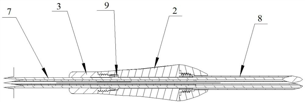
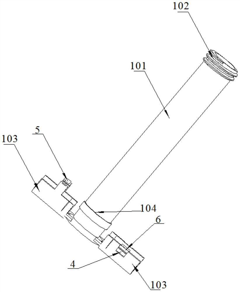
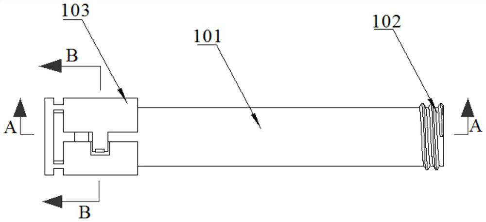
[0033] like Figure 2-Figure 5 As shown, a snap limit structure includes a limit tube body 101, the limit tube body 101 is a tubular structure, and has a through hole 1011 along the axial direction suitable for the booster tube 7 of the stent implanter to pass through, An axial end of the limiting tube body 101 is provided with an external thread 102 for threaded engagement with the handle 2 . The other axial end of the limiting tube body 101 is provided with a movable sleeve suitable for abutting against the fixed knob 3; The position tube body 101 is softly connected, so that the buckle 103 can be turned over relative to the position limit tube body 101 . One end (rear end) of each buckle 103 away from the fixing knob 3 is connected to the limiting tube body 101 , and the other end (front end) of the buckle 103 can be turned over relative to its connection end with the limiting tube body 101 . When locking, the buckle 103 is turned over to the outer circumference of the li...

Embodiment 2

[0041] In the first embodiment, during the release process, it is impossible to determine whether the fixing knob 3 is completely released. If the release is not complete, the release of the bracket will be blocked. figure 2 As shown, in this embodiment, a radially protruding limiting shoulder 104 is further provided outside the limiting tube body 101 . When the movable sleeve is buckled, the limiting shoulder 104 is located on the inner circumference of the movable sleeve. The outer diameter of the limiting shoulder 104 is larger than the inner diameter of the fixing knob 3 . The limiting shoulder 104 can realize the indication (indicating the position that the doctor can release) and the limiting function. When releasing, as long as the fixing knob 3 is in contact with the end face of the limiting shoulder 104, it means that the release is in place (eg. Figure 10 shown).

[0042] The sheath tube 8 and the handle 2 can be fixedly connected by the following structure: the s...


PUM


Abstract

The buckle limiting structure comprises a limiting pipe body suitable for a boosting pipe of the support imbedding device to penetrate through, one axial end of the limiting pipe body is provided with an external thread, and the other axial end of the limiting pipe body is provided with a movable sleeve suitable for being connected with a fixed rotary knob in an abutting mode; the movable sleeve is of a tubular structure formed by buckling at least two buckles, and the outer end of each buckle is in flexible connection with the limiting pipe body so that the buckles can turn over relative to the limiting pipe body. The buckle limiting structure is in threaded fixation with the handle, the buckle limiting structure serves as a middle adapter of the boosting tube and the fixed knob, the movable sleeve is used for abutting against the fixed knob, and the movable sleeve can be formed by buckling a plurality of buckles and can be detached, so that threaded connection of the fixed knob and the handle can be improved into sliding connection; when the support needs to be released, only the movable sleeve needs to be detached, the releasing speed is high, and operation is convenient.

Description

technical field [0001] The invention relates to the technical field of medical devices, in particular to a snap-fit ​​limiting structure and a stent implanter using the same. Background technique [0002] In stent placement surgery, a fixed knob is usually used to lock it to prevent misoperation during transportation or during surgery, such as figure 1 Shown is a schematic diagram of the existing stent implanter on the market. Through the threaded cooperation of the locking knob 10 and the outer sheath handle 11, the locking rubber ring 9 is compressed and locked, and the locking rubber ring 9 is under the action of force, and is tightly attached. Attached to the booster tube 7 to generate a larger coefficient of friction, so in the locked state, the bracket will not be released by misoperation and transportation. During the bracket placement (release) process, it is necessary to unscrew the locking knob 10 first, and then push the bracket to release. [0003] but figure ...

Claims


Application Information

Patent Timeline
Patent Type & Authority Applications(China)
IPC IPC(8): A61F2/95A61F2/962A61B90/00
CPCA61F2/95A61F2/9517A61F2/962A61B90/08A61F2002/9505A61B2090/0807
Inventor 周玉柳全乐陶凯孙婷婷檀涛鲍少鹏
Owner JIANGSU VEDKANG MEDICAL SCI & TECH
Why Eureka
Try Eureka