
Atmosphere-controllable heat treatment equipment

A technology of heat treatment equipment and atmosphere, applied in the field of variable temperature experimental equipment, can solve problems such as sample damage

Pending Publication Date: 2022-05-27
HEFEI UNIV OF TECH
View PDF0 Cites 0 Cited by
  • Summary
  • Abstract
  • Description
  • Claims
  • Application Information

AI Technical Summary

Problems solved by technology

[0006] Since the equipment has a fully enclosed inner cavity structure, the heating and cooling process of the sample can be in a vacuum or a protective atmosphere. The sample after multiple thermal stress cycles is not affected by environmental factors. Therefore, the sample has not failed after the test and is still It can continue to be used or carry out other tests, which solves the problem that samples are easily damaged by other environmental factors in previous test experiments

Method used


Image

  • Atmosphere-controllable heat treatment equipment
  • Atmosphere-controllable heat treatment equipment
  • Atmosphere-controllable heat treatment equipment

Examples


Embodiment 1

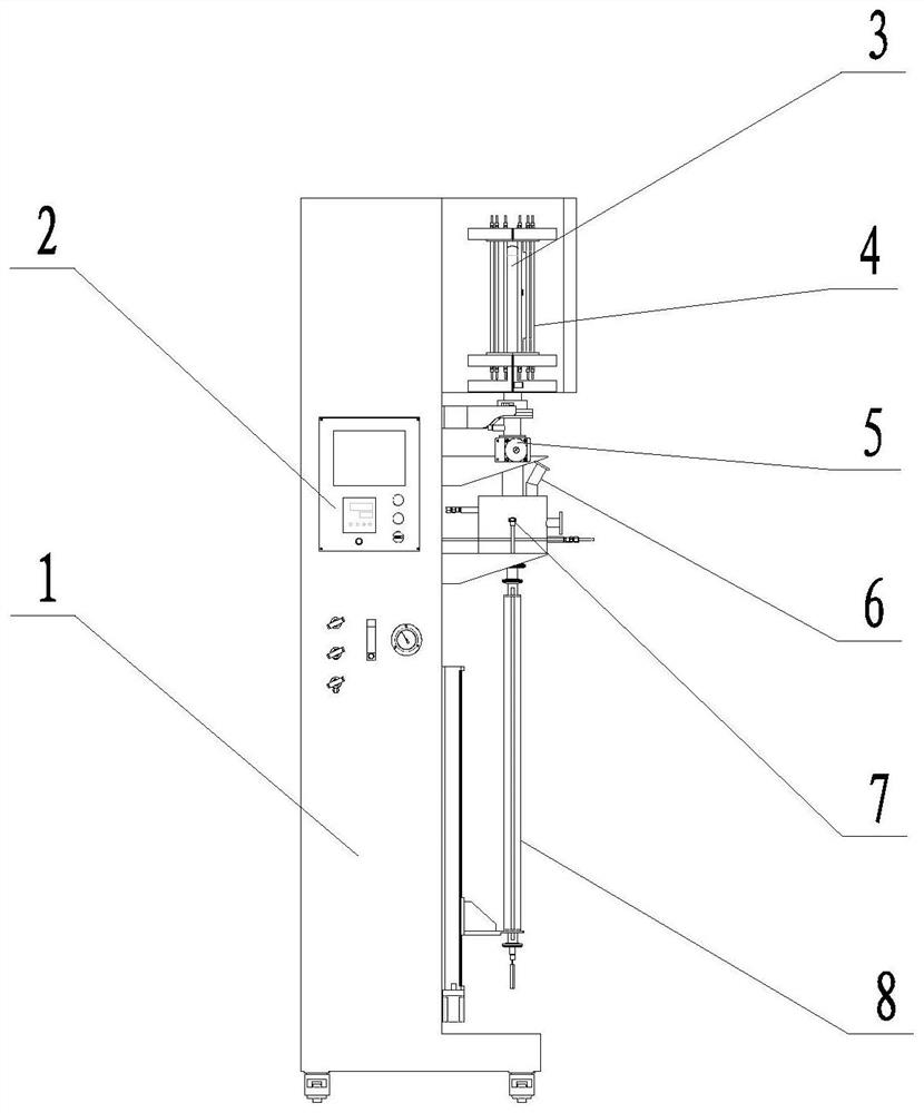
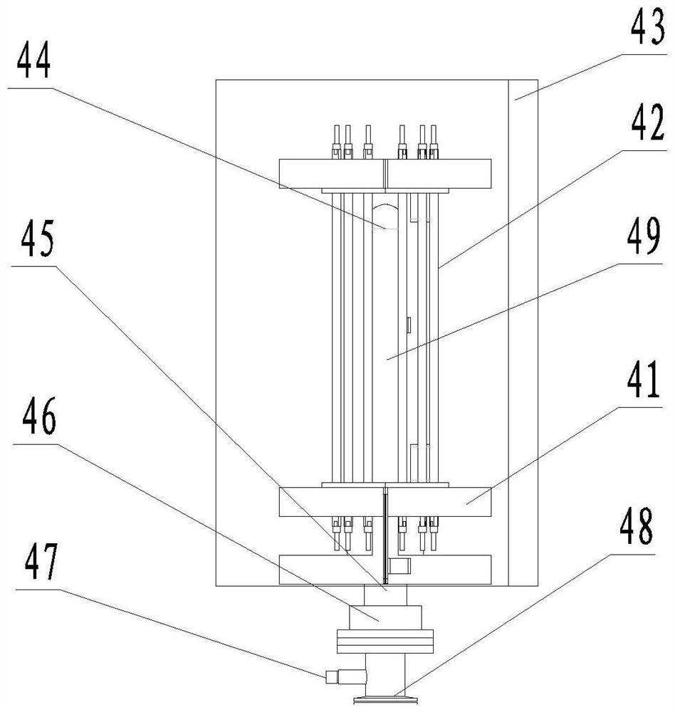
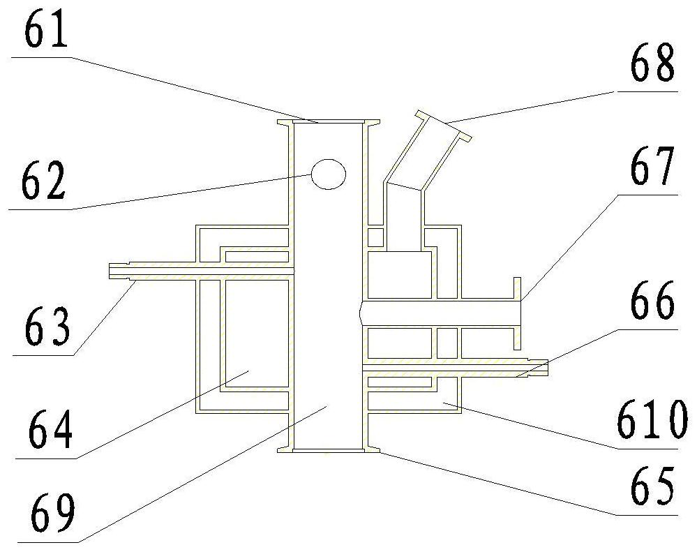
[0030] This embodiment discloses a heat treatment testing machine with a controllable atmosphere. The testing machine includes a main body 1, a control mechanism 2 and a testing mechanism 3; wherein the testing mechanism includes a heating system 4, a blocking structure 5, a cooling system 6, a lifting system The system 8 and the sample stage 7; the heating system 4 surrounds the furnace structure from the outside, and the furnace structure and the cooling system 6 have an inner cavity channel, and the two are connected by a blocking structure 5, and the blocking structure 5 controls the communication and blocking of the two, The lifting system 8 is docked with the other end of the cooling system 6 , and the sample stage 7 is located at the end of the lifting system 8 . The lifting system 8 can drive the sample stage 7 to move back and forth between the cooling system cavity 69 and the heating system cavity 49 . When the sample stage 7 moves up and down, it can ensure that the ...

Embodiment 2

[0039] This embodiment discloses a heat treatment testing machine with a controllable atmosphere. The testing machine includes a main body 1, a control mechanism 2 and a testing mechanism 3; wherein the testing mechanism includes a heating system 4, a blocking structure 5, a cooling system 6, a lifting system The system 8 and the sample stage 7; the heating system 4 contains a furnace body structure, and the furnace body structure and the cooling system 6 have an inner cavity channel, and the two are connected by a barrier structure 5, and the barrier structure 5 controls the connection and blocking of the two. The lifting system 8 is docked with the other end of the cooling system 6 , the sample stage 7 is located at the end of the lifting system 8 , and the lifting system 8 can drive the sample stage 7 to move back and forth between the cooling system cavity 69 and the heating system cavity 49 . When the sample stage 7 moves up and down, it can ensure that the placed sample i...

Embodiment 3

[0048] This embodiment discloses an environment simulation testing machine with a controllable atmosphere. The testing machine includes a main body 1, a control mechanism 2 and a testing mechanism 3; wherein the testing mechanism includes a heating system 4, a blocking structure 5, a cooling system 6, The lifting system 8 and the sample stage 7; the heating system 4 contains a furnace body structure, and the furnace body structure and the cooling system 6 have an inner cavity channel, and the two are connected by a barrier structure 5, and the barrier structure 5 controls the connection and blocking of the two, lifting and lowering. The system 8 is docked with the other end of the cooling system 6 , the sample stage 7 is located at the end of the lifting system 8 , and the lifting system 8 can drive the sample stage 7 to move back and forth between the cooling system cavity 69 and the heating system cavity 49 . When the sample stage 7 moves up and down, it can ensure that the p...


PUM


Abstract

The invention discloses atmosphere-controllable heat treatment equipment. The equipment comprises a main body mechanism, a control mechanism and a test mechanism, wherein the test mechanism comprises a heating system, a blocking structure, a cooling system, a lifting system and a sample table. The heating system internally comprises a furnace body structure, the furnace body structure and the cooling system are provided with inner cavity channels and are connected through a blocking structure, and the blocking structure controls connection and disconnection of the furnace body structure and the cooling system; the lifting system is in butt joint with the other end of the cooling system, the sample table is located at the end of a guide rod of the lifting system, and the lifting system drives the sample table through the guide rod to reciprocate between an inner cavity of the cooling system and an inner cavity of the heating system. In the up-and-down movement process of the sample table, the atmosphere environment in an inner cavity channel formed by the inner cavity of the heating system, the inner cavity of the cooling system and the corrugated pipe compressed by the lifting system is still kept. The control mechanism, the heating system, the cooling system and the lifting system are matched, the sample table can reach the specific temperature within the specific time, and the temperature control interval ranges from-200 DEG C to 1200 DEG C.

Description

technical field [0001] The invention relates to the field of variable temperature experimental equipment, in particular to a heat treatment equipment with a controllable atmosphere environment. Background technique [0002] In aerospace, marine, petroleum, nuclear energy and other high, precise and cutting-edge fields, many components require service materials with different functions. The materials used to prepare these parts often face extreme high temperature and low temperature conditions, requiring them to have a large service temperature range. At a higher service temperature, the material is subjected to large thermal stress, which will cause cracks or even cracks due to thermal fatigue, eventually leading to failure. Therefore, it is particularly important to evaluate the performance of materials against thermal cyclic stress. [0003] At present, there are many test platforms for evaluating the thermal cycle resistance of materials. In the thermal cycle test, the...

Claims


Application Information

Patent Timeline
IPC IPC(8): B01L7/00G01N25/00
CPCB01L7/5255G01N25/00B01L2300/1872B01L2300/1894B01L2300/024Y02P10/25
Inventor 谭晓月吴玉程徐清波罗来马
Owner HEFEI UNIV OF TECH
Learn More