Supercharge Your Innovation With Domain-Expert AI Agents!

Steel pipe mark jet printing equipment and steel pipe branch-by-branch mark jet printing method thereof

A technology for equipment brackets and steel pipes, which is applied to the field of steel pipe marking jet printing equipment and its steel pipe mark printing field, can solve the problems of mutual collision, wear of jet printing marks, low recognizable rate of marks, etc. The effect of low overall cost and improved recognizability

Pending Publication Date: 2022-05-27
BAOSHAN IRON & STEEL CO LTD
View PDF0 Cites 0 Cited by
  • Summary
  • Abstract
  • Description
  • Claims
  • Application Information

AI Technical Summary

Problems solved by technology

Since the steel pipes will be conveyed by rollers, rolled on the platform, and collided with each other in the basket during the production and transportation process, the existing steel pipe markings, whether it is printing pipe numbers, printing barcodes, or sticking self-adhesive labels There will always be the problem that the printed mark is worn or blocked by the rolling of the steel pipe, and the recognizable rate of the mark is not high

Method used


Image

  • Steel pipe mark jet printing equipment and steel pipe branch-by-branch mark jet printing method thereof
  • Steel pipe mark jet printing equipment and steel pipe branch-by-branch mark jet printing method thereof
  • Steel pipe mark jet printing equipment and steel pipe branch-by-branch mark jet printing method thereof

Examples


Embodiment Construction

[0033] In order to better understand the above technical solutions of the present invention, the technical solutions of the present invention are further described below with reference to the accompanying drawings and embodiments.

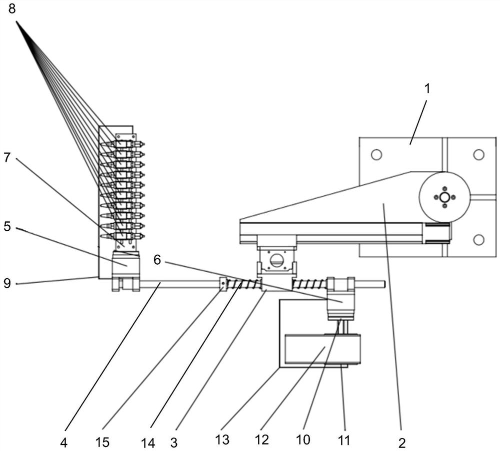
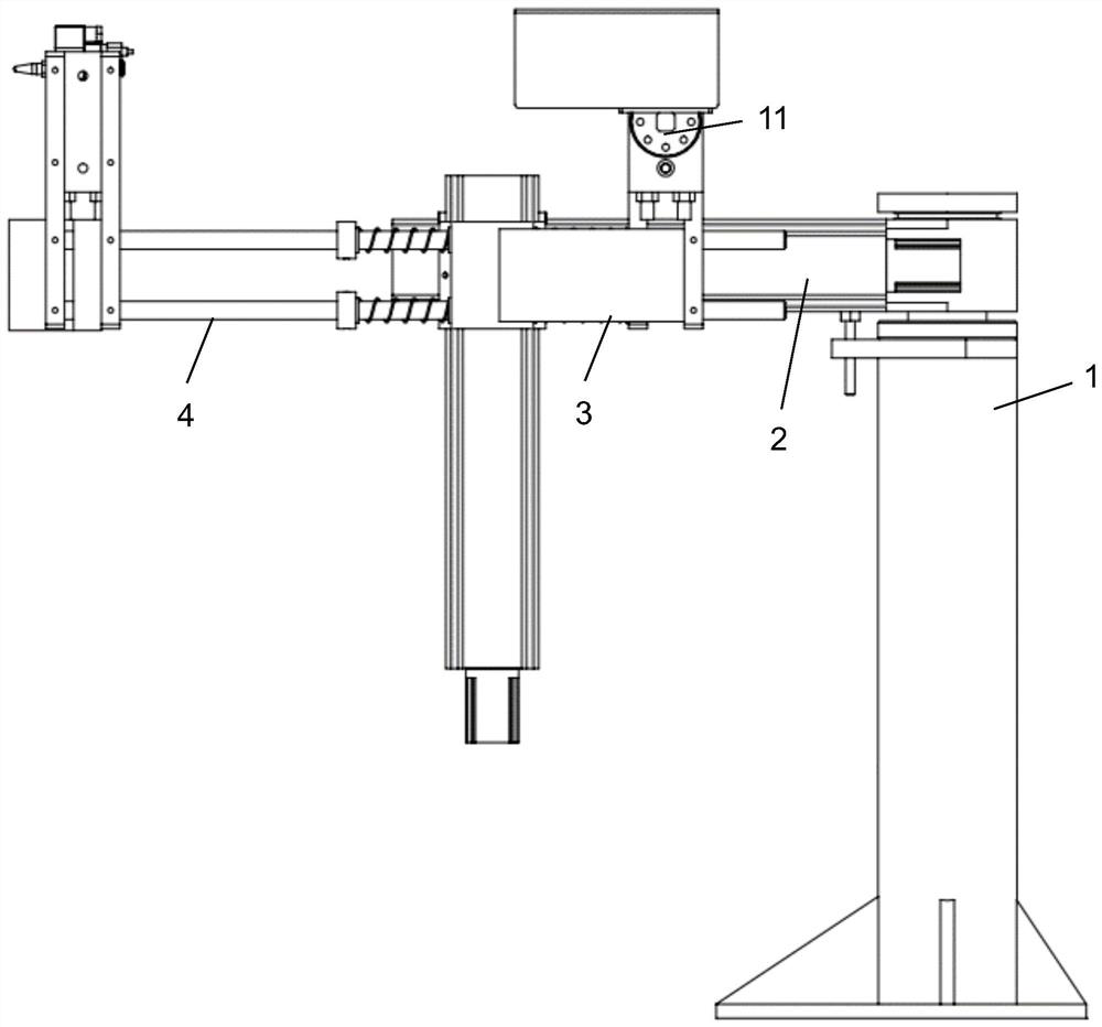
[0034] please combine figure 1 , figure 2 As shown in the figure, a steel pipe identification spray printing equipment provided by the present invention includes an equipment support 1, a swing rod 2 installed on the top of the equipment support 1, an optical axis seat 3 is installed on the swing rod 2, and an optical axis seat 3 is installed on the optical axis seat 3. The connecting rod 4 has a first rotating cylinder 5 mounted on the front end of the connecting rod 4 and a second rotating cylinder 6 mounted on the rear end of the connecting rod 4 .

[0035] A spray gun seat fixing member 7 is installed on the first rotating cylinder 5 , and a spray gun seat 8 and a spray gun cleaning box 9 are installed on the spray gun seat fixing member 7 . ...


PUM


Abstract

The invention discloses steel pipe mark jet printing equipment and a steel pipe branch mark jet printing method thereof. The steel pipe mark jet printing equipment comprises an equipment support and a swing rod arranged on the equipment support, an optical axis seat is arranged on the swing rod, a connecting rod is arranged on the optical axis seat, a first rotating air cylinder is arranged at the front end of the connecting rod, and a second rotating air cylinder is arranged at the rear end of the connecting rod; a spray gun seat fixing piece is arranged on the first rotating air cylinder, and a spray gun seat is arranged on the spray gun seat fixing piece; and a spray head is arranged on the second rotating cylinder. According to the invention, the problem that the jet printing mark is worn and shielded due to steel pipe transportation, rotation, collision, on-site oil stain and pipe body oxide skin falling can be overcome or improved.

Description

technical field [0001] The invention relates to on-line tracking technology of pipe materials, and more particularly, to a steel pipe identification jet printing equipment and a pipe mark jet printing method thereof. Background technique [0002] In the traditional steel pipe production line, the steel pipe material tracking generally adopts PLC control signal and manual auxiliary tracking method to realize the batch tracking of the pipe material, that is, according to the furnace number or trial batch number, the steel pipe is divided into multiple production batches before and after. Online tracking of production batch data. The whole process by branch tracking is less realized. Steel pipe production is a discrete and discontinuous processing and production mode. During the production process, unqualified steel pipe products are inevitably offline and reworked. The offline steel pipe data is generally recorded manually or manually entered into the computer. Due to the lac...

Claims


Application Information

Patent Timeline
IPC IPC(8): B21C51/00
CPCB21C51/005Y02P90/30
Inventor 林海左宏志代卫余勇
Owner BAOSHAN IRON & STEEL CO LTD
Features
  • R&D
  • Intellectual Property
  • Life Sciences
  • Materials
  • Tech Scout
  • Unparalleled Data Quality
  • Higher Quality Content
  • 60% Fewer Hallucinations
Learn More