Eureka AIR delivers breakthrough ideas for toughest innovation challenges, trusted by R&D personnel around the world.

Guide rail type chuck mechanism

A rail-type and chuck technology, which is applied in chucks, climate sustainability, and final product manufacturing, to achieve force balance, ensure clamping accuracy and processing accuracy, and make the manufacturing process simple.

Pending Publication Date: 2022-05-27
CHINA ELECTRONIC TECH GRP CORP NO 38 RES INST
View PDF6 Cites 1 Cited by
  • Summary
  • Abstract
  • Description
  • Claims
  • Application Information

AI Technical Summary

Problems solved by technology

[0009] The technical problem to be solved by the present invention is: how to solve the problem of complex structure of the chuck in the prior art.

Method used


Image

  • Guide rail type chuck mechanism
  • Guide rail type chuck mechanism
  • Guide rail type chuck mechanism

Examples


Embodiment 1

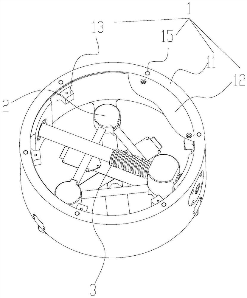
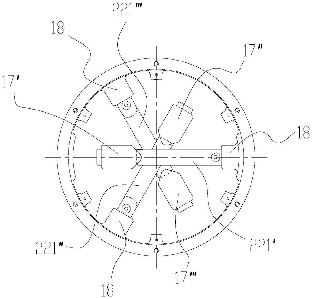
[0053] like figure 1 As shown, the rail-type chuck mechanism includes a chuck assembly 1, a plurality of claw assemblies 2, and a chuck drive mechanism 3. The chuck assembly 1 is a cylindrical cavity, and the multiple claw assemblies 2 have a regular polygonal structure. The drive mechanism 3 is connected to one of the jaw assemblies 2 . In this embodiment, there are three jaw assemblies 2 , and the three jaw assemblies 2 are in a regular triangle structure, and the center of the regular triangle coincides with the circle center of the chuck assembly 1 .

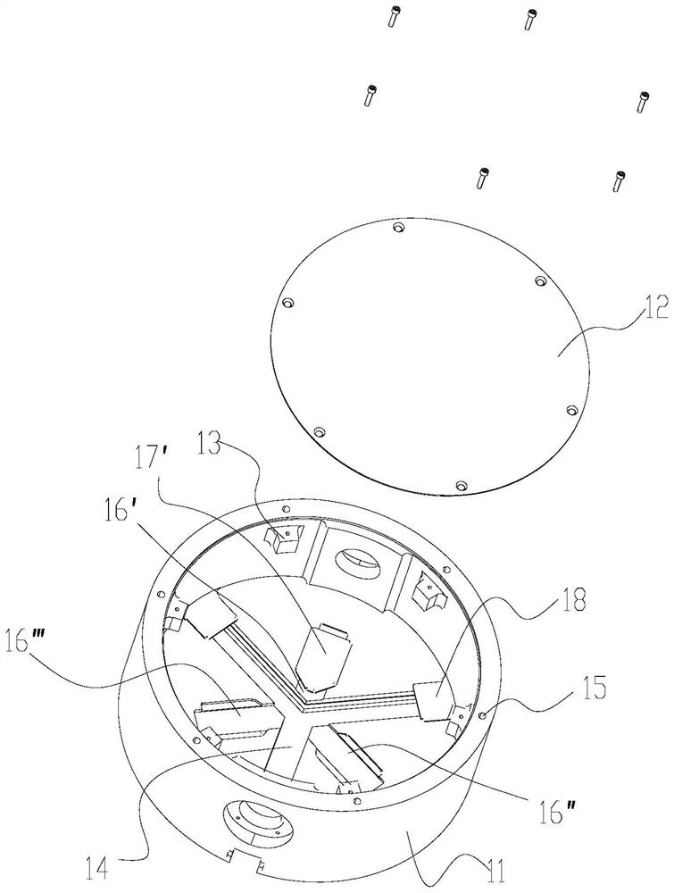
[0054] like figure 2 As shown, the chuck assembly 1 includes a chuck body 11, a chuck cover 12, a fixed boss 13, a chute 14, and a threaded hole 15. The chuck body 11 is a cylindrical cavity with an open top, so The bottom end of the chuck body 11 has three chute 14, the chute 14 is a structure that penetrates the bottom, the three chute 14 are connected at the center, and the cross section of the chute 14 is rectangular....

Embodiment 2

[0074] like Figure 13 , Image 6 As shown, in this embodiment, on the basis of Embodiment 1, the chuck drive mechanism 3 includes a drive screw 31 and a connecting block 32. Correspondingly, the top end of one of the claw assemblies 2 is connected with the connecting block 32. This In the embodiment, the connecting block 32 is connected to the first claw assembly 2 ′. In this embodiment, the connecting block 32 and the top of the claw guide rail 23 ′ are integral structures. Of course, it can also be a split structure and connected by bolts or the like.

[0075] The connecting block 32 is a cylindrical block structure with a waist-shaped cross section, and has a trapezoidal threaded hole 321 penetrating through it on the horizontal plane, and the driving screw 31 is connected with the trapezoidal threaded hole 321 .

[0076] like Figure 14 , Figure 15 As shown, the two ends of the drive screw 31 are mounting sections, the mounting section is connected to the cylindrical ...


PUM


Abstract

The invention discloses a guide rail type chuck mechanism which comprises a chuck assembly, a plurality of clamping jaw assemblies and a chuck driving mechanism, the clamping jaw assemblies are of a regular polygon structure, each clamping jaw assembly comprises a clamping jaw body, a clamping jaw sliding block and a clamping jaw guide rail, one side of each clamping jaw sliding block is connected with the corresponding clamping jaw body, and the other side of each clamping jaw sliding block is connected with the corresponding clamping jaw guide rail. The clamping jaw sliding blocks are connected with the chuck assemblies in a sliding mode, the clamping jaw sliding blocks of the adjacent clamping jaw assemblies are in linkage, the chuck driving mechanism is connected with the clamping jaw guide rail of one clamping jaw assembly, and when the chuck driving mechanism enables the clamping jaw assembly connected with the chuck driving mechanism to move relative to the circle center of the regular polygon structure or the circle center of the regular polygon structure opposite to the circle center of the regular polygon structure or the circle center of the regular polygon structure opposite to the circle center of the regular polygon structure opposite to the circle center of the regular polygon structure. All the clamping jaw assemblies move relative to or away from the circle center of the regular polygon structure. The device has the beneficial effects that the multiple clamping jaw assemblies are accurately and rapidly controlled to be synchronously opened or closed, automatic centering is achieved, the structure is simple, and the manufacturing process is simple.

Description

technical field [0001] The invention relates to the field of mechanical processing equipment, in particular to a chuck mechanism. Background technique [0002] The three-jaw chuck mechanism is usually used as the clamping device of the machine tool. The installation of the three-jaw chuck mechanism on the machine tool usually has two forms. One is that the three-jaw chuck is installed on the end of the machine tool spindle, the tool is fixed, and the three-jaw chuck The disc clamps the workpiece and rotates around the machine tool spindle to complete the processing. The other is that the three-jaw chuck clamps the workpiece and fixes it on the worktable, and the tool revolves around the workpiece to complete the processing; the three-jaw chuck can also be like a vise. Installed on the workbench, clamping the bar, used in all kinds of fitter operations. [0003] The three-jaw chuck mechanism is divided into three-jaw chuck mechanism in the form of pneumatic type, hydraulic t...

Claims


Application Information

Patent Timeline
IPC IPC(8): B23B31/103
CPCB23B31/103Y02P70/50
Inventor 石磊杨双根孙远涛周骏石方亮廖延鹏曹强束洋潘永强王小宇郑少鹏钱磊
Owner CHINA ELECTRONIC TECH GRP CORP NO 38 RES INST
Why Eureka
Eureka Blog
Learn More