
Endoscope machining clamp and enoscope machining method

A refracting mirror, machining technology, applied in the direction of metal processing machinery parts, manufacturing tools, metal processing equipment, etc., can solve the problem that the quality of the mirror surface is difficult to guarantee

Pending Publication Date: 2022-05-27
苏州众捷汽车零部件股份有限公司
View PDF8 Cites 0 Cited by
  • Summary
  • Abstract
  • Description
  • Claims
  • Application Information

AI Technical Summary

Problems solved by technology

[0003] The core of mirror processing is to ensure the position accuracy, but because of the different support conditions required for the processing of the low-beam mirror surface and the high-beam mirror surface, the low-beam mirror surface must be used as the support when milling the high-beam mirror surface, otherwise the quality of the mirror surface is difficult to guarantee due to insufficient strength of the workpiece, so The traditional process requires at least two clamping to complete

Method used


Image

  • Endoscope machining clamp and enoscope machining method
  • Endoscope machining clamp and enoscope machining method
  • Endoscope machining clamp and enoscope machining method

Examples


Embodiment 1

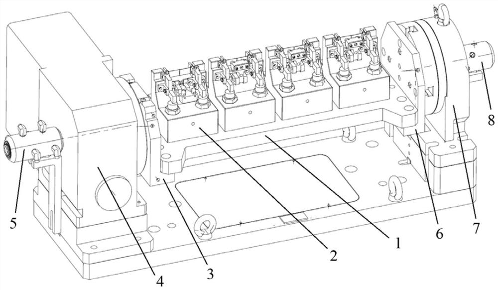
[0031] This embodiment provides a refracting mirror machining fixture, such as figure 1 As shown, the machining fixture comprises a bridge plate 1 and four identical fixture units 2 located on the bridge plate 1 . In other examples, other numbers of clamp units 2 (eg two, three or more) may also be used. Using a plurality of fixture units 2 is beneficial to improve the efficiency of machining. Inside the bridge plate 1 is a hydraulic oil circuit and an air circuit, which are respectively communicated with the hydraulic components and air pressure sensors of each fixture unit 2 . The bridge plate 1 is connected with the horizontal CNC turntable 4 through the left L-shaped connecting plate 3 . At the same time, the rear end of the CNC turntable 4 is equipped with a hydraulic oil rotary joint 5, the fixed end of which is connected to the oil outlet of the hydraulic station, and the rotating end is connected to the oil circuit of the left L-shaped connecting plate 3, and the lef...

Embodiment 2

[0036] The present embodiment also provides a method for machining a refracting mirror, which mainly includes the following steps:

[0037] (1) Put the four workpieces (refractors to be processed) into the positioning seats of their respective fixture units, stick to the positioning surfaces, and clamp the positioning pins.

[0038] (2) Start the NC program, the clamping cylinder lifts the lever pressing plate, each lever pressing plate clamps the workpiece, and starts the processing of the shape of the refractor blade.

[0039] (3) The CNC turntable is rotated to the low beam mirror surface processing angle, and the low beam mirror surface is rough and finely milled.

[0040] (4) Rotate the CNC turntable to the processing angle of the high beam mirror surface, lift the floating support device (folded state) to support the low beam mirror surface processed in step (3), and then rough and finely mill the high beam mirror surface.

[0041] (5) The CNC turntable rotates to the ori...


PUM


Abstract

The invention discloses an enoscope machining clamp and an enoscope machining method.The enoscope machining clamp comprises a bridge plate, clamp units, a first connecting plate and a second connecting plate, and one end of the bridge plate is connected with a numerical control rotary table through the first connecting plate; the other end of the bridge plate is connected with a tailstock through the second connecting plate, the clamp unit comprises a clamp body, a positioning device, a clamping device and a floating supporting device, and the clamp unit is fixed to the bridge plate through the clamp body. The positioning device is used for positioning an enoscope workpiece to be machined on the clamp unit, the clamping device is used for clamping the positioned enoscope workpiece, and the floating supporting device selectively provides floating supporting for a low beam mirror face of the enoscope workpiece. By means of the device, machining of the low-beam mirror surface and the high-beam mirror surface of the enoscope can be met in one-time clamping, and therefore the position precision and the mirror surface machining precision are guaranteed.

Description

technical field [0001] The invention relates to the technical field of machining, in particular to a refracting mirror machining fixture and a refracting mirror machining method. Background technique [0002] The refracting mirror is used to reflect the light emitted by the light-emitting diode (LED) light source into a set direction. When working, there are a group of LED light sources on the upper and lower sides, one group is used as low beam and the other group is used as high beam. In addition to the high processing precision of the mirror surface itself, the refracting mirror also has high positional precision relative to the reference surface. [0003] The core of mirror processing is to ensure the position accuracy, but due to the different support conditions required for the processing of the low beam mirror and the high beam mirror, the low beam mirror should be used as the support when milling the high beam mirror, otherwise the mirror quality is difficult to gua...

Claims


Application Information

Patent Timeline
Patent Type & Authority Applications(China)
IPC IPC(8): B23Q3/08B23Q1/25
CPCB23Q3/082B23Q1/25
Inventor 解柏解晓宇
Owner 苏州众捷汽车零部件股份有限公司
Learn More