
Novel pressurizing mechanism for hydraulic tire vulcanizing machine and hydraulic tire vulcanizing machine

A tire vulcanization and pressurization mechanism technology, which is applied in tires, applications, household appliances, etc., can solve the high cost of configuration and maintenance costs of the pressurization mechanism, difficulty in controlling the synchronization of the pressurization mechanism, and the reduction of piston rod tension and other issues, to achieve the effect of reducing configuration costs and later use and maintenance costs, reducing configuration costs, and shortening the length

Pending Publication Date: 2022-05-27
华澳科技(苏州)股份有限公司
View PDF0 Cites 0 Cited by
  • Summary
  • Abstract
  • Description
  • Claims
  • Application Information

AI Technical Summary

Problems solved by technology

[0005] Nowadays, the pressurization mechanism generally adopts a pressurized cylinder with a double-rod structure. The piston rod is hollow, and the lower rod penetrates the pressurized cylinder through the hollow piston rod, which causes the outer diameter of the piston rod to be too large, resulting in a decrease in the tension of the piston rod. Small, the pressurization pressure of the pressurization mechanism has to be satisfied by increasing the bore and the number of configurations of the pressurization cylinder in the axial direction. The configuration cost and maintenance cost of the pressurization mechanism have always been high, and the more pressurization cylinders, The more difficult it is to control the synchronization of the pressurization mechanism

Method used


Image

  • Novel pressurizing mechanism for hydraulic tire vulcanizing machine and hydraulic tire vulcanizing machine
  • Novel pressurizing mechanism for hydraulic tire vulcanizing machine and hydraulic tire vulcanizing machine
  • Novel pressurizing mechanism for hydraulic tire vulcanizing machine and hydraulic tire vulcanizing machine

Examples


Embodiment Construction

[0038] In order to facilitate the understanding of the present invention, the present invention will be described more comprehensively and in detail below with reference to the accompanying drawings and preferred embodiments of the specification, but the protection scope of the present invention is not limited to the following specific embodiments. It should be noted that the embodiments of the present invention and the features of the embodiments may be combined with each other under the condition of no conflict.

[0039] In order to realize the purpose of the present invention, the technical scheme provided by the present invention is:

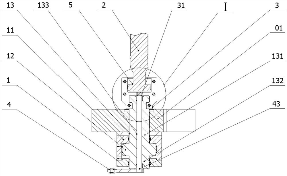
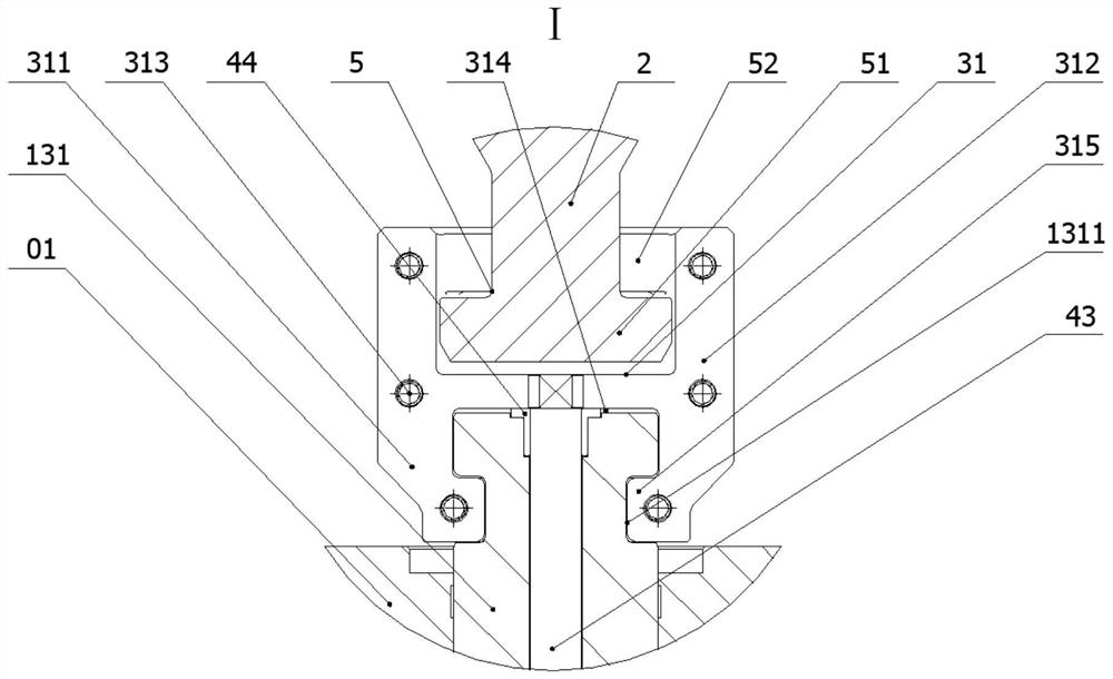
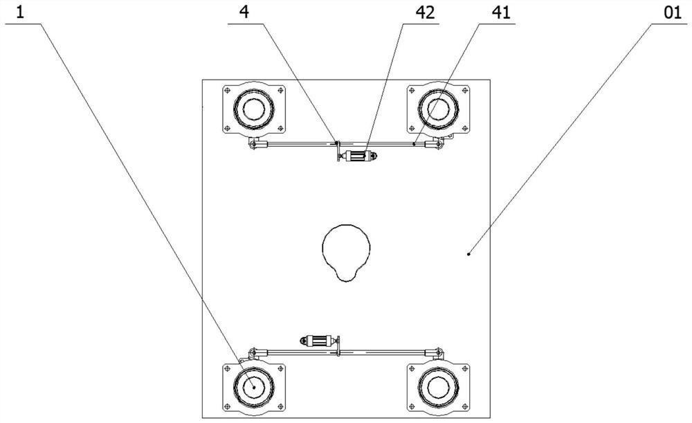
[0040] In some embodiments of the invention, such as figure 1 , 4, 6, 7, a new type of pressurizing mechanism for hydraulic tire vulcanizers is disclosed, including: pressurizing oil cylinder 1, upper pull rod 2, pull down rod assembly 3 and loosening / locking device 4; pressurized oil cylinder 1. Set on the lower surface of the base 01 in a...


PUM


Abstract

The invention discloses a novel pressurizing mechanism for a hydraulic tire vulcanizing machine. The novel pressurizing mechanism comprises a pressurizing oil cylinder, an upper pull rod, a lower pull rod assembly and a locking / unlocking device, wherein the pressurizing oil cylinder comprises a first piston rod or comprises the first piston rod and a second piston rod; the lower pull rod assembly comprises a lower pull rod, and the lower pull rod is locked with or separated from the upper pull rod through axial reciprocating rotation; the locking / unlocking device is connected with the lower pull rod and used for driving the lower pull rod to rotate in a reciprocating mode in the circumferential direction. The lower pull rod is connected with the piston rod outside the pressurizing oil cylinder, so that the length of the lower pull rod can be effectively shortened, the outer diameter of the piston rod can be reduced, the tension of a single oil cylinder is increased, the configuration number of the pressurizing oil cylinders is reduced, and the configuration cost of the pressurizing mechanism is remarkably reduced; and the lifting synchronism and stability of the pressurizing oil cylinder can be conveniently controlled.

Description

technical field [0001] The invention relates to the technical field of vulcanization equipment, in particular to a novel pressurizing mechanism for a hydraulic tire vulcanizer and a hydraulic tire vulcanizer. Background technique [0002] With the development of society and the increasingly rich living standards of people, especially since the 21st century, the automobile industry has been in a stage of vigorous development, and has driven the lasting prosperity of related industries. As one of the important accessories for automobiles, the development of tires is particularly eye-catching. , because the safety performance of the tire directly determines the safety factor of the car, which in turn affects the overall performance of the car. Because of this, the innovation and progress of tire production equipment has always been the focus of attention of technicians in the industry, among which tire vulcanizers are is a typical representative of it. [0003] In the prior ar...

Claims


Application Information

Patent Timeline
IPC IPC(8): B29C35/02B29C37/00B29L30/00
CPCB29D30/0662
Inventor 朱理波黄桂强张正罗江兴明
Owner 华澳科技(苏州)股份有限公司
Learn More