
Automatic film tearing mechanism based on products for production

An automatic, high-quality product technology, applied in the direction of final product manufacturing, packaging, climate sustainability, etc., can solve the problems of residual protective film on the surface of the product, poor appearance of FPC, and easy breakage of the protective film, so as to avoid the problem of residual glue and reduce the The problem of residual fracture and the effect of avoiding sliding and falling off

Pending Publication Date: 2022-05-27
珠海韦田智科精密机械有限公司
View PDF0 Cites 0 Cited by
  • Summary
  • Abstract
  • Description
  • Claims
  • Application Information

AI Technical Summary

Problems solved by technology

[0002] During the production process of many products, the surface needs to be covered with a protective film, and then the protective film needs to be removed. At present, the commonly used tearing methods in the industry are tape tearing or high-pressure air tearing, but in the FPC industry, customers have certain requirements for the FPC surface. Requirements, the tape tearing method is easy to introduce residual glue to the surface of the FPC, resulting in poor appearance of the FPC. At the same time, the high-pressure air tearing method is better for some products that are easy to blow off and the adhesive force of the protective film is small, but for some parts. For strong products, it is easy to tear the protective film during the process of tearing off the protective film, resulting in poor protective film residue on the surface of the product. At the same time, due to factors such as the shape of the protective film and uneven distribution of adhesive force with the product, high-pressure air blows off the protective film. , the tail of the protective film is easily broken

Method used


Image

  • Automatic film tearing mechanism based on products for production
  • Automatic film tearing mechanism based on products for production
  • Automatic film tearing mechanism based on products for production

Examples


Embodiment Construction

[0032] The technical solutions in the embodiments of the present invention will be clearly and completely described below with reference to the accompanying drawings in the embodiments of the present invention. Obviously, the described embodiments are only a part of the embodiments of the present invention, but not all of the embodiments. Based on the embodiments of the present invention, all other embodiments obtained by those of ordinary skill in the art without creative efforts shall fall within the protection scope of the present invention.

[0033] see Figure 1-7 , the present invention provides an embodiment:

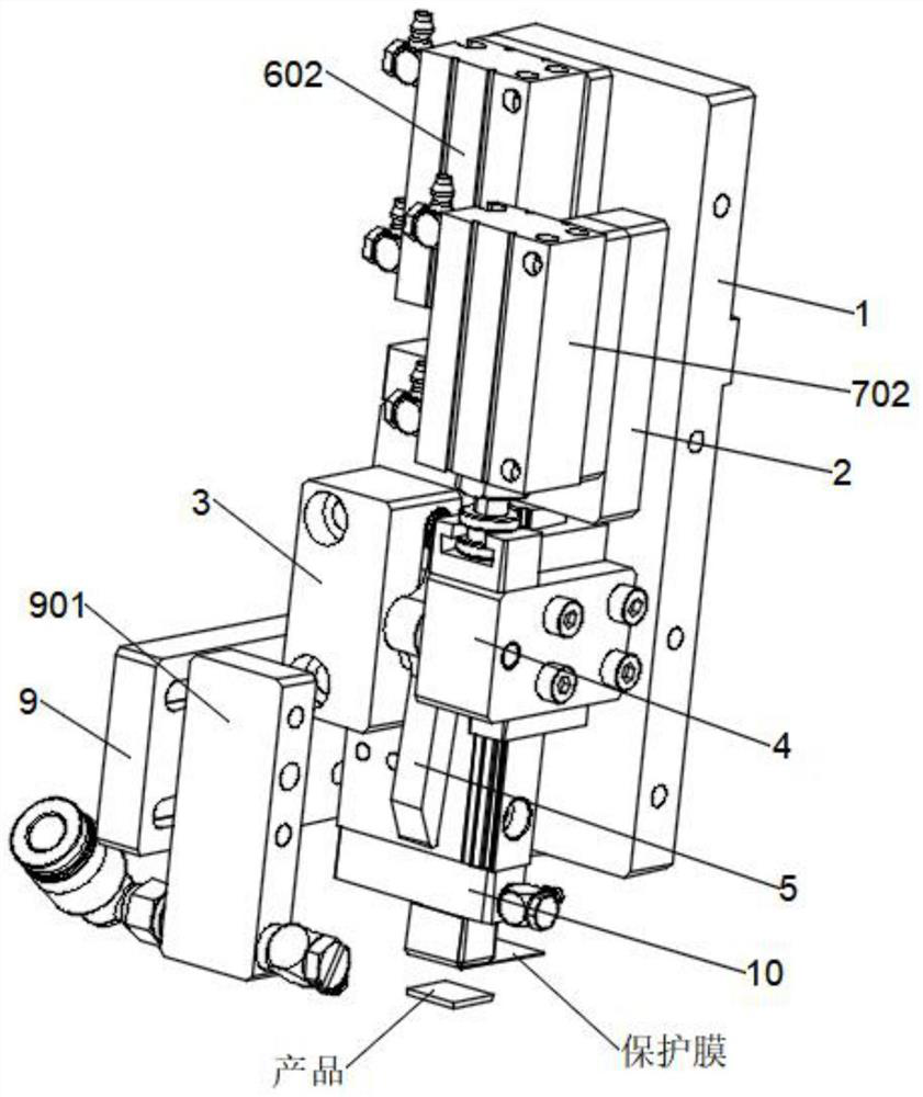
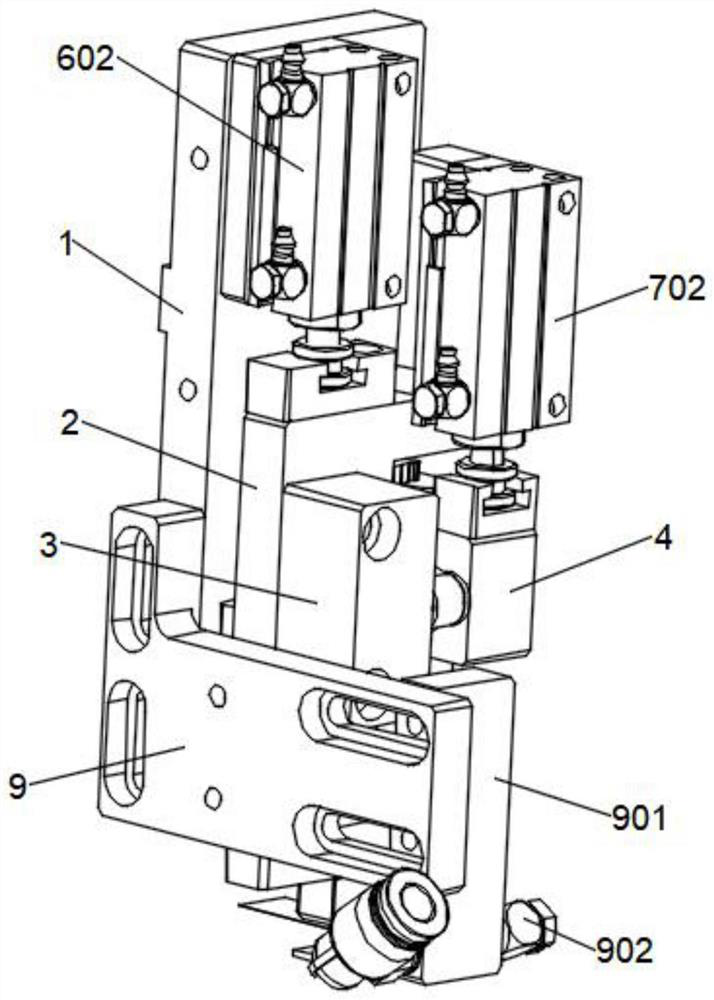
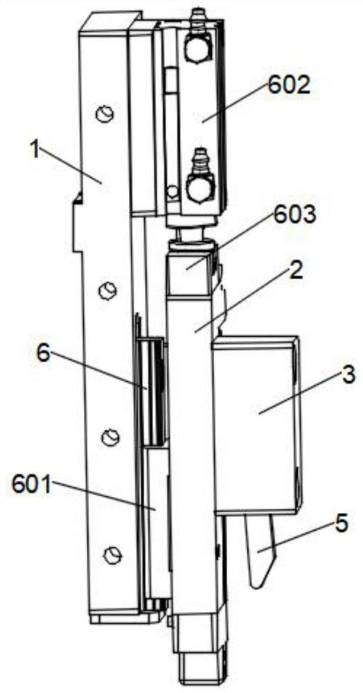
[0034]An automatic film tearing mechanism based on production products, comprising a fixed installation substrate 1, a special-shaped lifting plate 2, a side end fixing block 3 and a side lifting block 4, and a pressing component is provided at the upper left of the front surface of the fixed installation substrate 1, The special-shaped lifting plate 2 is arrang...


PUM


Abstract

The invention relates to the technical field of film tearing devices, in particular to a product automatic film tearing mechanism based on production, which comprises a fixed mounting base plate, a special-shaped lifting plate, a side end fixing block and a side edge lifting block, the special-shaped lifting plate is arranged on the front side of the fixed mounting base plate through a downward pressing assembly, and the special-shaped lifting plate is in a vertical Z shape. A product is tightly pressed on the surface of a loading table through the lower end of a bottom mounting block, one end of a protective film is tilted through blowing of a high-pressure nozzle, the tilted end of the protective film can be firmly sucked under the negative pressure action of a vacuum negative-pressure suction nozzle, and the tilted end of the protective film can be clamped to the front side surface of a special-shaped lifting plate through the lower end of a strip-shaped protective film clamping plate; and then the product is driven to move in cooperation with the material carrying table, automatic film tearing can be completed, the problem of adhesive residues caused by adhesive tape tearing can be effectively solved, and the problem of protective film breakage residues caused by high-pressure air tearing is greatly solved.

Description

technical field [0001] The invention relates to the technical field of film tearing devices, in particular to an automatic film tearing mechanism based on production products. Background technique [0002] In the production process of many products, the surface needs to be covered with a protective film, and then the protective film needs to be removed. At present, the commonly used film tearing methods in the industry are tape tearing film or high-pressure air tearing film, but in the FPC industry, customers have certain requirements on the surface of FPC. Requirements, the tape tearing method is easy to introduce residual glue to the surface of the FPC, resulting in poor appearance of the FPC. At the same time, the high-pressure air tearing film method is easy to blow off part of the film, and the protective film has a low adhesion. Strong product, it is easy to tear the protective film in the process of tearing off the protective film, resulting in poor residue of the pro...

Claims


Application Information

Patent Timeline
Patent Type & Authority Applications(China)
IPC IPC(8): B65B69/00
CPCB65B69/00Y02P70/50
Inventor 韩志刚梁达保郭涛柴光俊马本翔
Owner 珠海韦田智科精密机械有限公司
Learn More