
Pipe and bar material distributing mechanism and method

A material-distributing mechanism and pipe-rod technology, applied in conveyors, vibrating conveyors, conveyor objects, etc., can solve problems such as low efficiency, time-consuming and labor-intensive, personnel injuries, etc., to improve personal safety factor, reduce manual intervention, use low cost effect

Active Publication Date: 2022-05-27
CHINA NAT HEAVY MACHINERY RES INSTCO
View PDF11 Cites 0 Cited by
  • Summary
  • Abstract
  • Description
  • Claims
  • Application Information

AI Technical Summary

Problems solved by technology

[0004] The invention provides a pipe and rod material sorting mechanism and a material sorting method to overcome the difficulty of sorting in the traditional manual unbundling method, which is easy to cause the tube and rod to be entangled when unbundling in the prior art, and cannot be smoothly spread out and flattened. Multi-person cooperation is required, and the dismantling process is likely to cause personal injury. For super long tubes and rods, it is time-consuming and laborious, and the efficiency is extremely low.

Method used


Image

  • Pipe and bar material distributing mechanism and method
  • Pipe and bar material distributing mechanism and method
  • Pipe and bar material distributing mechanism and method

Examples


Embodiment 1

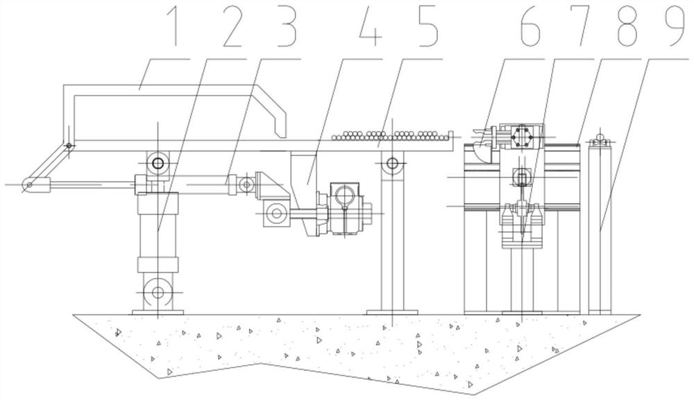
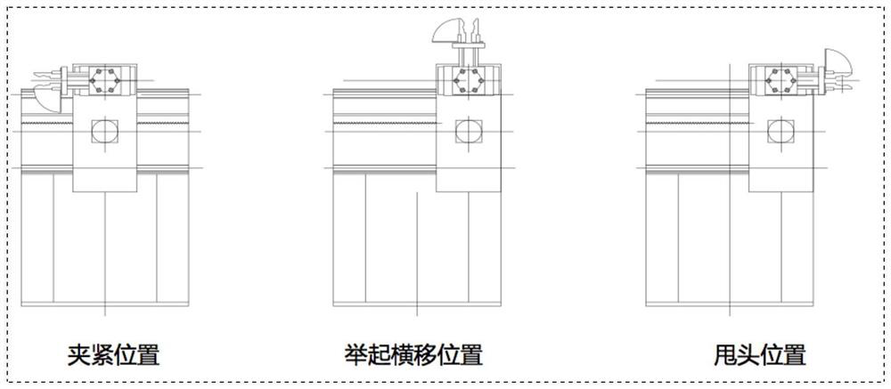
[0025] like Figure 1-3 and Figure 5 As shown in the figure, a pipe and rod material distributing mechanism includes a turning frame 1, a shaking oil cylinder 2, a turning frame opening and closing oil cylinder 3, a fine adjustment device for the opening and closing degree of the turning frame 4, a material shaking and bulk material frame 5, and a clamping and turning head device 6 , the feeder 7, the clamping device base 8 and the discharge roller table 9, the material shaking and bulk material rack 5 includes a flat plate 5-1 and a support frame 5-2, the flat plate 5-1 is arranged horizontally, and the lower part of the flat plate 5-1 is Connect the shaking oil cylinder 2, the turning frame opening and closing degree fine-tuning device 4 and the support frame 5-2 in turn from left to right. The lower left end of the frame 1 is connected to the left end of the flat plate 5-1 and the flip frame 1 is located on the upper side of the flat plate 5-1, the clamping and flipping h...

Embodiment 2

[0028] On the basis of Embodiment 1, the flip frame 1 includes an upper plate, a left plate and a right plate, the left end of the upper plate is connected to the left plate at the bottom, the right end of the upper plate is connected to the right plate at the bottom, and the lower end of the left plate is rotatably connected to the The left end; the rotating connection is convenient to open or close the flip frame 1; preferably, the lower end of the left plate is connected to the left end of the flat plate 5-1 through a pin, the connection method is simple and easy to operate; the upper plate, the left plate and the right plate are combined or integrated Structure; choose according to actual needs, with strong selectivity.

[0029] Preferably, the lower right end of the flip frame 1 is not connected to the flat plate 5-1.

[0030] The lower right end of the turning frame 1 is the lower end of the right plate. When the shaking cylinder 2 shakes, it is ensured that the pipe and...

Embodiment 3

[0039] On the basis of Embodiment 2, when the shaking oil cylinder 2 shakes, it shakes up and down. The up-and-down shaking makes full use of the action of gravity, so that the tube and bar slide out of the crimping area of ​​the turning frame along the gap under the action of gravity, from disorder to one layer at most two layers, the principle and operation are simple.

[0040] Preferably, the support frame 5-2 is an up and down telescopic support frame; it is convenient to control the lifting and lowering of the right part of the flat plate 5-1.

[0041] Preferably, the turning frame opening and closing degree fine adjustment device 4 includes an oil cylinder and a lifter, the oil cylinder is connected to the lifter, the power output end of the oil cylinder is connected to the power input end of the turning frame opening and closing oil cylinder 3, and the power output end of the lifter is connected to the bottom of the flat plate 5-1. ; The oil cylinder opens or closes the...


PUM


Abstract

The invention belongs to the technical field of metallurgical equipment, and particularly provides a pipe and bar material distributing mechanism and method.The pipe and bar material distributing mechanism comprises an overturning frame, a shaking oil cylinder, an overturning frame opening and closing oil cylinder, an overturning frame opening and closing degree fine adjustment device, a material shaking and dispersing frame, a clamping and overturning head shaking device, a material distributor, a clamping device base and a discharging roller way, and the material shaking and dispersing frame comprises a flat plate and a supporting frame; the problems that during existing bundle opening, the pipes and the bars are prone to being wound and cannot be smoothly scattered and flattened, a traditional manual bundle opening mode is difficult in sorting, multi-person cooperation is needed, personnel injury is prone to being caused in the disassembling process, and time and labor are wasted and efficiency is extremely low for the ultra-long pipes and the bars are solved. Manual intervention is reduced, the personal safety coefficient of workers is improved, and the device has the advantages of being simple in structure, high in working efficiency and low in use cost.

Description

technical field [0001] The invention belongs to the technical field of metallurgical equipment, and particularly relates to a pipe and rod material distributing mechanism and a material distributing method. Background technique [0002] For small-diameter pipes and bars, the method of bundling is generally used for transportation. However, when this method of transportation reaches the place where the equipment needs to be loaded, it is easy to cause the pipes and bars to be entangled when unbundling, and it cannot be spread out smoothly. The methods of unbundling are all manual operations, that is, people bundling, flattening, and aligning the ultra-long thin tubes and bars. In this process, manual sorting is difficult for the ultra-long winding tubes and bars, requiring the cooperation of multiple people. The dismantling process is easy to cause personal injury. For super-long pipes and bars, it is time-consuming and labor-intensive, and the efficiency is extremely low. ...

Claims


Application Information

Patent Timeline
Patent Type & Authority Applications(China)
IPC IPC(8): B65G27/10B65G47/248B65G47/90
CPCB65G27/10B65G47/248B65G47/904B65G2201/0217
Inventor 刘邯涛刘磊武晓斌孔立群吕江
Owner CHINA NAT HEAVY MACHINERY RES INSTCO
Learn More