Underwater grouting equipment for large-volume cavity

An underwater grouting and large-volume technology, which is applied in hydropower, construction, infrastructure engineering, etc., can solve the problems of secondary gaps, failure to consider, and slurry escape, so as to prevent slurry backflow and improve perfusion quality effect

Active Publication Date: 2022-05-27
CHINA POWER CONSRTUCTION GRP GUIYANG SURVEY & DESIGN INST CO LTD
View PDF6 Cites 0 Cited by
  • Summary
  • Abstract
  • Description
  • Claims
  • Application Information

AI Technical Summary

Problems solved by technology

[0003] In the above technical solution, it is proposed that the positioning of the underwater grouting hole is completed through the probe nozzle, but it does not take into account that after the grouting is completed, the slurry in the cavity will flow back along the grouting hole, resulting in The slurry escapes, so there will be gaps in the solidified slurry again, resulting in abnormal engineering quality; therefore, the present invention provides an underwater grouting equipment for large-volume cavities

Method used


Image

  • Underwater grouting equipment for large-volume cavity
  • Underwater grouting equipment for large-volume cavity
  • Underwater grouting equipment for large-volume cavity

Examples


Embodiment 1

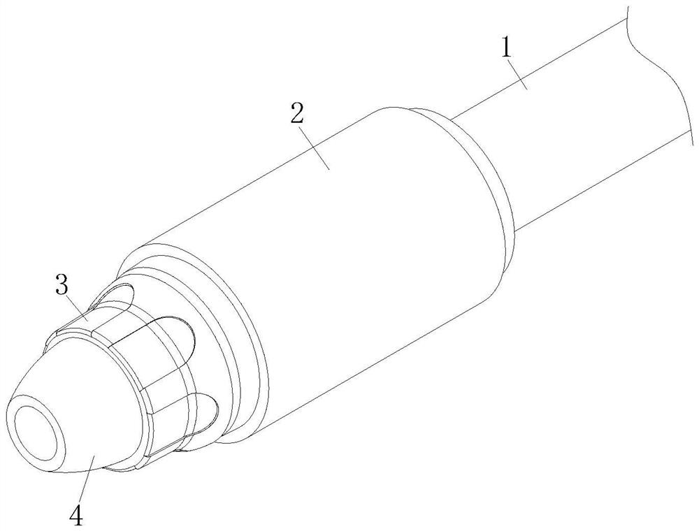
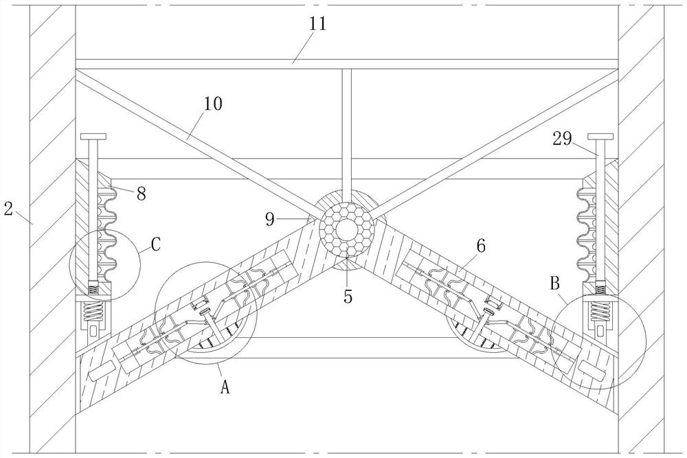
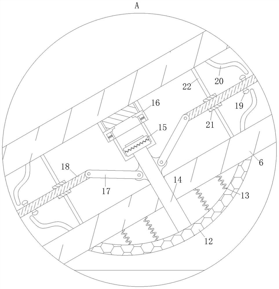
[0040] Example 1. A kind of underwater grouting equipment for large volume cavity, composition such as Figure 1-4 Shown, comprising a grouting tube 1, the grouting tube 1 end is connected to a fully automatic dust-free mixer, the grouting tube 1 at the other end of the socket is connected to the stop housing 2, the stop housing 2 away from the grouting tube 1 end of the socket 3, the connection ring 3 away from the check case 2 end of the socket is connected to the nozzle 4, the stop housing body 2 is fixed inside the support pin 5, the support pin 5 is provided externally with two separators 6, the two of the separator plate 6 is hinged by a torsion spring on the outside of the support pin 5, The baffle 6 is fixed with a rubber plate 7 at one end away from the support pin 5, the plywood 7 is connected to the inner wall of the stop housing 2 sliding connection; when working, the slurry is injected into the grout pipe 1, and then the slurry will be injected into the cavity through ...

Embodiment 2

[0049] Example 2, an underwater grouting apparatus for a large volume cavity, constitutes such as Figure 5 As shown, compared to Example 1, using another embodiment, the difference is that the limit ring 8 is connected internally with a reciprocating rod 29, the bottom end of the reciprocating rod 29 is fixed with a vibration spring 30, the reciprocating rod 29 is fixed to the transmission block 31 near the center of the check housing 2, the transmission block 31 away from the reciprocating rod 29 on one side is provided with a wave rod 32, the wave rod 32 away from the reciprocating rod 29 at one end fixed with a wave housing 33, the wave housing 33 is fixed to the limit ring 8 fixed connection When working, when the slurry is perfused, it will also collide with the reciprocating rod 29, and the impact force will act on the vibration spring 30 through the reciprocating rod 29, thereby causing the reciprocating flutter of the vibration spring 30, and the reciprocating rod 29 will ...


PUM


Abstract

The invention discloses underwater grouting equipment for a large-volume cavity. The device comprises a grouting pipe, the grouting pipe is connected with a non-return shell, the non-return shell is connected with a connecting ring, and the connecting ring is connected with a spray head; a supporting pin is fixedly arranged in the non-return shell, the outer portion of the supporting pin is hinged to the head end of a partition plate through a torsional spring, and the tail end of the partition plate is movably connected with the inner wall of the non-return shell. The two partition plates are arranged to be used in cooperation with the torsional spring, the two partition plates are folded during grouting so as to be separated from the non-return shell, slurry can be poured smoothly, when slurry flows back, the partition plates make contact with the non-return shell to seal the non-return shell, and therefore the slurry is prevented from flowing back, and the grouting efficiency is improved. Therefore, the effects of preventing the slurry from flowing back and improving the pouring quality are achieved.

Description

Technical field [0001] The present invention relates to the technical field of water conservancy and hydropower engineering, in particular a kind of underwater grouting equipment for large volume cavity. Background [0002] A Chinese patent disclosed no. CN209243729U discloses an underwater grouting hole drilling equipment, comprising a first support plate, the first support plate is provided with a first chute on one side of the first support plate; under the joint action of the turntable, the rope collection disc, the wire collection rope and the second motor, the height of the probe device can be adjusted according to the underwater conditions, thereby reducing the wear degree of the probe nozzle, ensuring the service life of the probe nozzle, near the grout hole, the first motor works, in the first bearing, the first shaft, the second bearing, Under the joint action of the second shaft, threaded column and thread cap, the position of the perforation device can be adjusted, so...

Claims


Application Information

Patent Timeline
Patent Type & Authority Applications(China)
IPC IPC(8): E02D15/06
CPCE02D15/06Y02E10/20
Inventor 陈小明肖德序张广辉肖逸飞罗海燕
Owner CHINA POWER CONSRTUCTION GRP GUIYANG SURVEY & DESIGN INST CO LTD
Why Eureka
Try Eureka