Connecting and locking device for building templates

A locking device and construction formwork technology, which is applied to the connection parts of formwork/formwork/work frame, buildings, building structures, etc., can solve the problems of poor connection stability and inability to connect formwork with different angles, and achieve rotation stability , save connection time, and achieve precise connection effects

Active Publication Date: 2022-05-27
义乌建投巨匠建设有限公司
View PDF5 Cites 2 Cited by
  • Summary
  • Abstract
  • Description
  • Claims
  • Application Information

AI Technical Summary

Problems solved by technology

[0005] In order to overcome the shortcomings of poor connection stability in the above-mentioned prior art and the inability to connect templates with different angles, the technical problem to be solved by the present invention is to provide a connection with better stability, which can adjust the angle Locking device for building formwork connection for connection of different formwork

Method used


Image

  • Connecting and locking device for building templates
  • Connecting and locking device for building templates
  • Connecting and locking device for building templates

Examples


Embodiment 1

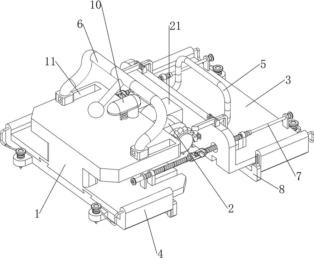
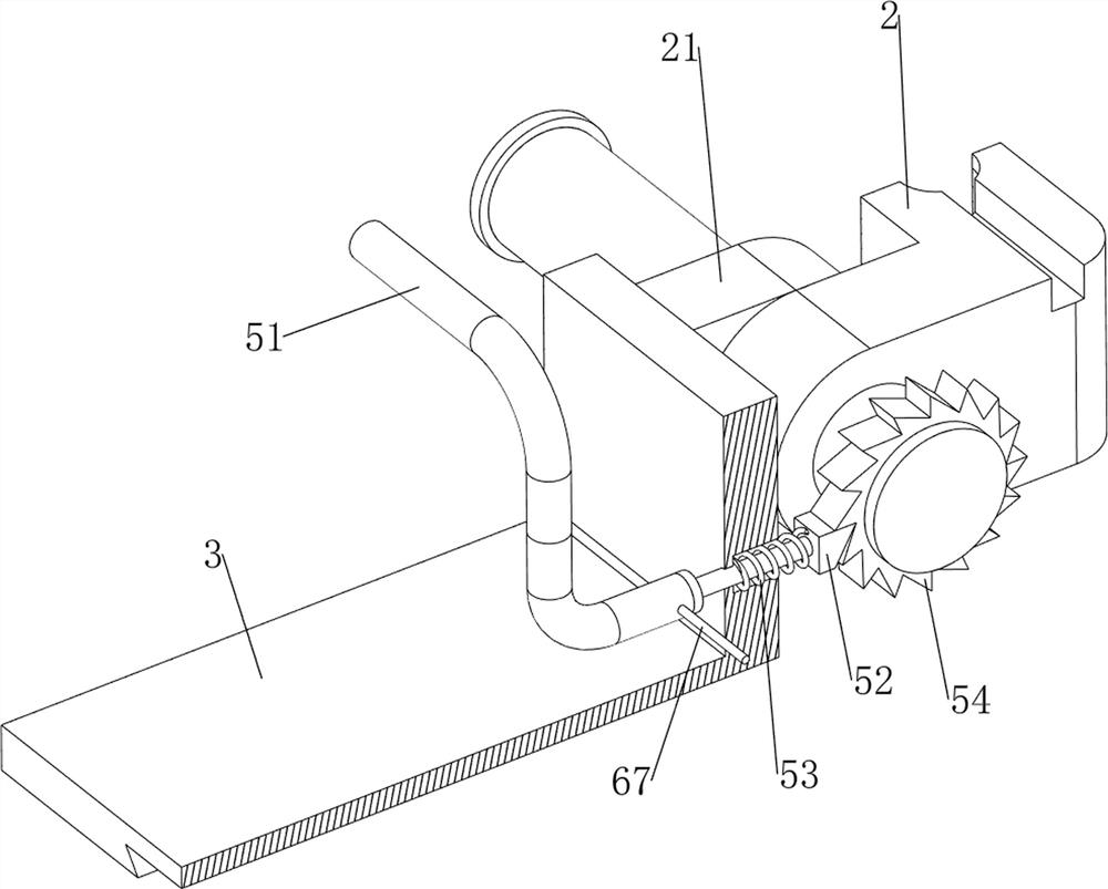
[0030] A locking device for building formwork connection, such as figure 1 , figure 2 , Image 6 , Figure 7 and Figure 9 As shown, it includes a T-shaped frame 1, a first connecting spring 12, a first hinge block 2, a second hinge block 21, an L-shaped plate 3, an installation mechanism 4, an adjustment mechanism 5 and a locking mechanism 6. The T-shaped frame 1 A cavity is opened on the right side, a first hinge block 2 is slidably arranged in the cavity, a first connecting spring 12 is connected between the first hinge block 2 and the T-shaped frame 1, and the right part of the first hinge block 2 rotates through There is a shaft, a second hinge block 21 is bolted on the shaft, an L-shaped plate 3 is bolted on the right side of the second hinge block 21, the top of the T-frame 1 is symmetrically opened with sliding grooves 11 on the front and rear sides, and the T-frame An installation mechanism 4 is arranged between the 1 and the L-shaped plate 3 , an adjustment mech...

Embodiment 2

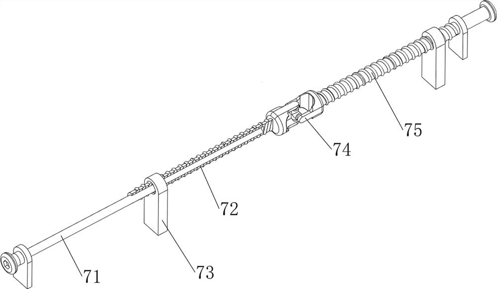
[0036] On the basis of Example 1, as figure 1 , Image 6 and Figure 8 As shown, an auxiliary mechanism 7 is also included. The auxiliary mechanism 7 includes a guide rod 71, a first screw rod 72, a second nut 73, a coupling 74 and a second screw rod 75. The sides are symmetrically welded with second nuts 73 in the front and rear, and the second nuts 73 on the left and right sides slide through the T-frame 1 and the L-shaped plate 3 respectively. The guide rods 71 ​​of the two nuts 73, the guide rods 71 ​​are hingedly sleeved with a first screw rod 72, the first screw rod 72 is threaded through the adjacent second nut 73, and both the front and rear sides of the top of the T-frame 1 are rotatable. A second screw rod 75 is provided, the second screw rod 75 is opposite to the thread on the first screw rod 72 , and a coupling 74 is bolted between the second screw rod 75 and the first screw rod 72 on the same side.

[0037] When the two templates are approached, the rightward m...

Embodiment 3

[0039] On the basis of Example 2, as figure 1 , Figure 5 and Image 6 As shown, it also includes a limiting mechanism 8. The limiting mechanism 8 includes a limiting silicone plate 81, a guide tube 82 and a second pulling rope 83. The opposite sides of the two sliding plates 41 are slidably provided with a limiting template. The limit silica gel plate 81, the two sliding plates 41 are separated from each other with a guide tube 82 running through the front and rear symmetrically, and the upper sides of the two limit silica gel plates 81 are symmetrically provided with a second pull rope for power transmission. 83. The tail end of the second pulling rope 83 is slidably penetrated through the adjacent guide tube 82 and connected with the adjacent screw 43.

[0040] The operator makes the opposite sides of the left and right templates contact the side of the left and right limit silica gel plates 81 away from each other, so that the template can be quickly aligned with the sli...


PUM


Abstract

The invention relates to a connecting and locking device, in particular to a connecting and locking device for building formworks. The connecting and locking device for the building formworks is good in connecting stability and capable of connecting formworks with different angles. The connecting and locking device for the building formwork comprises a T-shaped frame, a first connecting spring, a first hinge block, a second hinge block and the like, a cavity is formed in the right side of the T-shaped frame, the first hinge block is arranged in the cavity in a sliding mode, the first connecting spring is connected between the first hinge block and the T-shaped frame, and a shaft rod rotationally penetrates through the right portion of the first hinge block; the shaft rod is sleeved with a second hinge block. The formworks are fixed through the screws, the two formworks are made to be close to each other, then the hollow blocks are clamped through the clamping plates, so that the formworks can be stably connected together, and the formworks with different angles can be connected through cooperation of the first hinge blocks and the second hinge blocks and rotation of the T-shaped frames.

Description

technical field [0001] The invention relates to a connection and locking device, in particular to a connection and locking device for building formwork. Background technique [0002] Building formwork is a temporary support and protective structure, and it is a tool often used in construction. When using this type of formwork, it is necessary to connect and lock two adjacent formwork, so as to make the support of the formwork more stable and safe. , when the locking device of the prior art is used for the connection and locking of the building formwork, it is necessary to use the iron nails to press the abutting members on the device against the supporting members on the side of the formwork and the supporting members on the bottom surface respectively. The stability of the connection in this way is And the firmness is poor and inconvenient to use. [0003] According to the patent authorization publication number CN211257832U and the announcement date of 20200814, a connect...

Claims


Application Information

Patent Timeline
Patent Type & Authority Applications(China)
IPC IPC(8): E04G17/00
CPCE04G17/00
Inventor 赖唯瑾
Owner 义乌建投巨匠建设有限公司
Why Eureka
Try Eureka