LED lamp with good heat dissipation effect
A technology for LED lamps and heat dissipation effects, which is applied in the direction of lighting and heating equipment, components of lighting devices, and damage prevention measures for lighting devices. Damage and other issues
- Summary
- Abstract
- Description
- Claims
- Application Information
AI Technical Summary
Problems solved by technology
Method used
Image
Examples
Embodiment 1
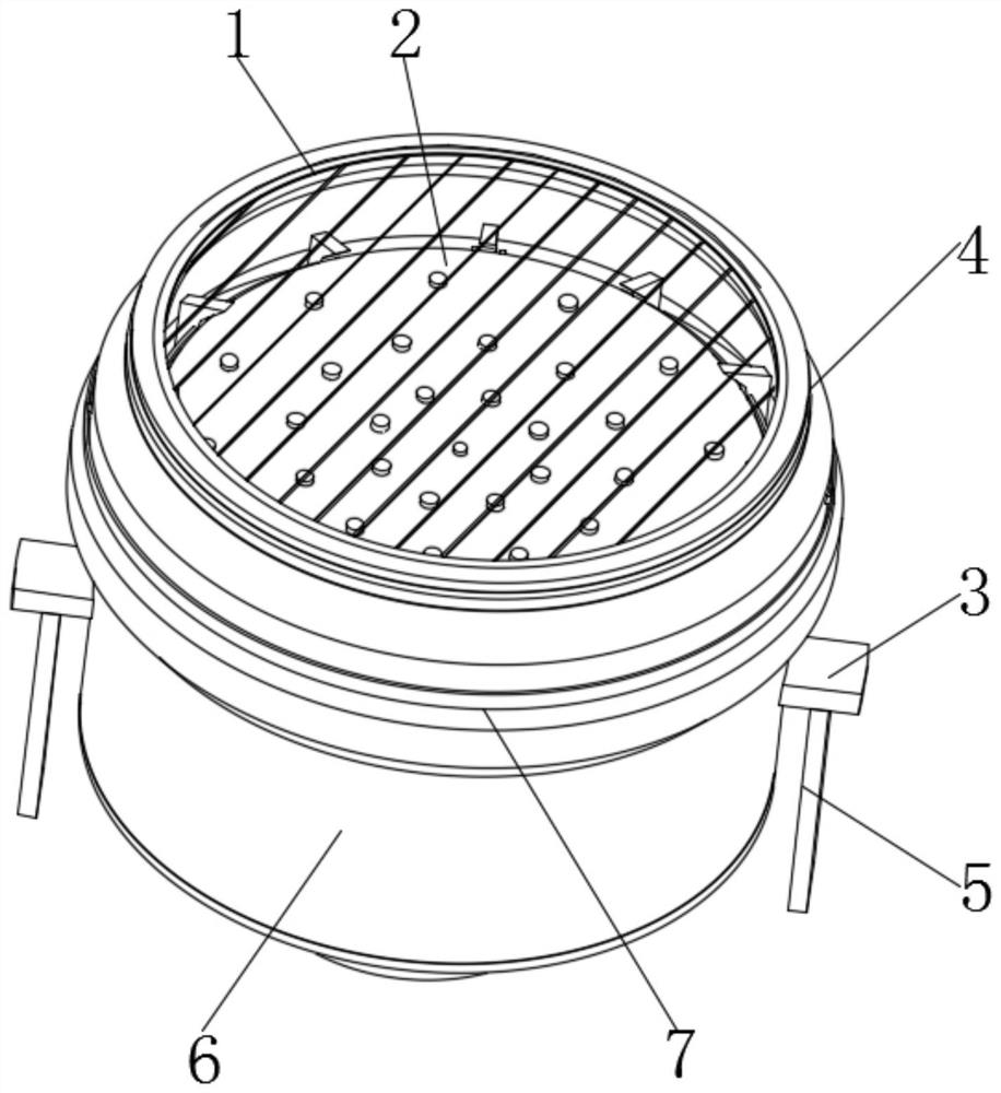
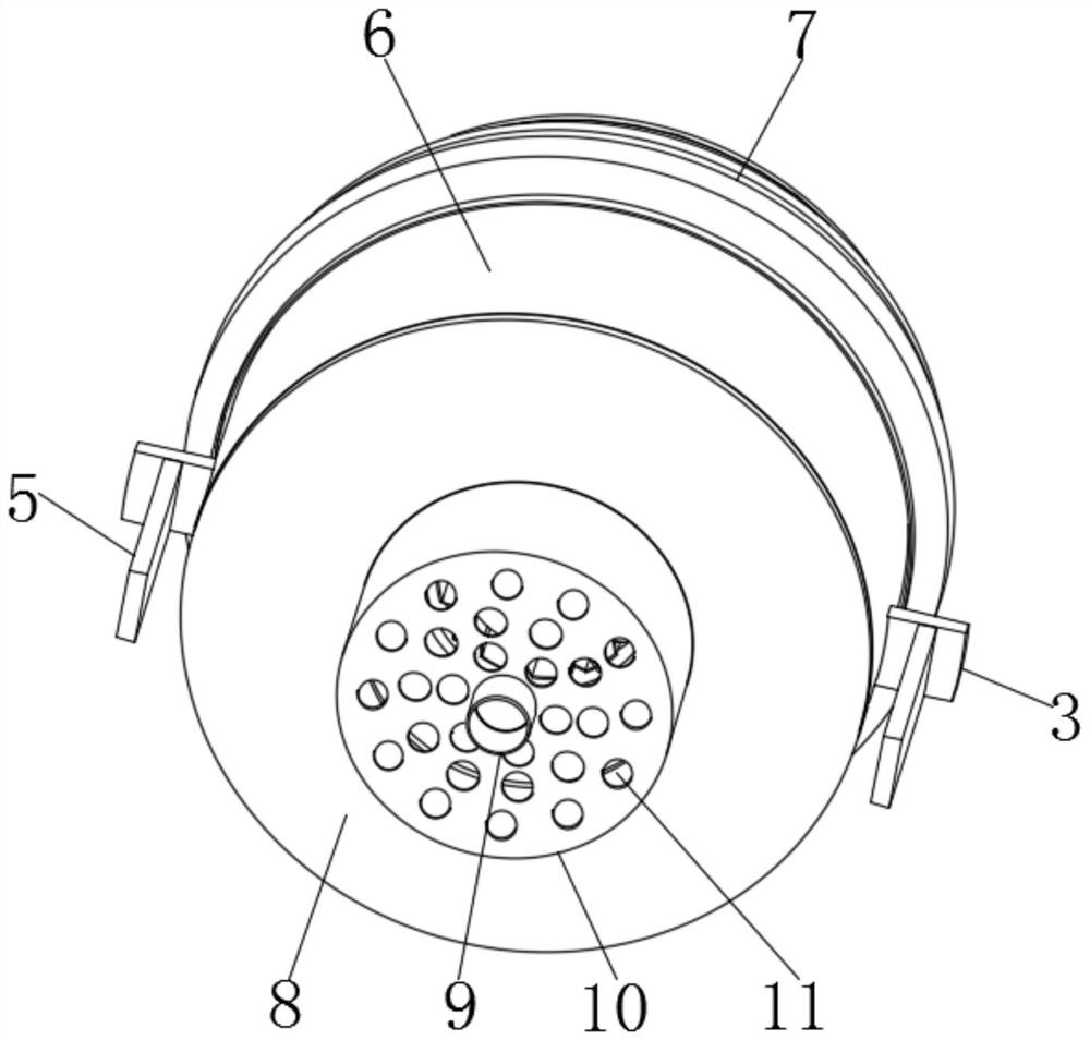
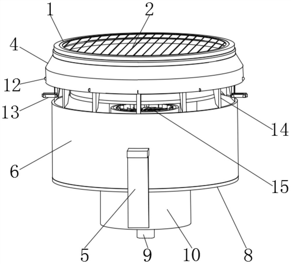
[0049] like Figure 1-Figure 12 As shown, an LED lamp with good heat dissipation effect includes a lampshade main body 6, an upper lampshade 4 and a fan 15. The inner wall of the lampshade main body 6 is connected with a heat dissipation fin 14, and the outer wall of the heat dissipation fin 14 is connected to the upper The inner walls of the lampshade 4 are connected to each other, the heat dissipation fins 14 are in a ring structure, and the heat dissipation fins 14 are surrounded by a number of fins 32 around the center of the circle. Two of the fins 32 are provided with chute 29. A second rotating shaft 30 is slidably connected in the chute 29, and two ends of the second rotating shaft 30 are respectively connected with a first connecting rod 13 and a second connecting rod 33, the first connecting rod 13 and the second connecting rod 33 A first rotating shaft 28 is connected between, and a connecting block 31 is sleeved on the outer wall of the first rotating shaft 28, and...
Embodiment 2
[0059] Based on the LED lamp with good heat dissipation effect provided by the first embodiment of the present application, the second embodiment of the present application proposes another LED lamp with good heat dissipation effect. The second embodiment is only a preferred mode of the first embodiment, and the implementation of the second embodiment will not affect the independent implementation of the first embodiment. The second embodiment of the present invention will be further described below with reference to the accompanying drawings and embodiments.
Embodiment 1
[0060] Based on the first embodiment, the difference between the second embodiment and the first embodiment is that the second embodiment is as follows: Figure 13-Figure 19 As shown, a bottom washer 38 is threadedly connected to the outer ring of the upper end of the upper lampshade 4, and the outer ring of the bottom washer 38 is surrounded by a plurality of pad supports 34 around its axis, and a connection is provided between the plurality of pad supports 34. Mechanism 36, the connecting mechanism 36 includes a first connecting rod 3601, a first T-shaped groove 3604 is opened on one side of the first connecting rod 3601, and a sliding condition 3603 is slidably connected in the first T-shaped groove 3604 , the sliding member 3603 has an H-shaped structure, one end of the sliding member 3603 is provided with a second connecting bar 3602, and one side of the second connecting bar 3602 is provided with a second T-shaped groove 3605, and the second T The groove 3605 forms a sli...
PUM
 Abstract
Description
Claims
Application Information
 - R&D
- Intellectual Property
- Life Sciences
- Materials
- Tech Scout
- Unparalleled Data Quality
- Higher Quality Content
- 60% Fewer Hallucinations
Browse by: Latest US Patents, China's latest patents, Technical Efficacy Thesaurus, Application Domain, Technology Topic, Popular Technical Reports.
© 2025 PatSnap. All rights reserved.Legal|Privacy policy|Modern Slavery Act Transparency Statement|Sitemap|About US| Contact US: help@patsnap.com


