Dynamic aging device and method for non-transparent bridge PCIe switching circuit

A switching circuit, non-transparent technology, applied in the direction of measuring devices, electronic circuit testing, measuring device casings, etc., can solve the problem of unable to provide PCIe switching circuit burn-in excitation signals, reduce the density of PCIe switching circuits on a single board, and unacceptable test costs and other issues, to achieve the effect of saving test cost, reducing design difficulty, and highly reliable transmission

Pending Publication Date: 2022-05-27
XIAN MICROELECTRONICS TECH INST
View PDF0 Cites 0 Cited by
  • Summary
  • Abstract
  • Description
  • Claims
  • Application Information

AI Technical Summary

Problems solved by technology

Due to the strict electrical characteristics requirements and complex functions of PCIe, the existing burn-in box cannot provide burn-in excitation signals that can meet the requirements of PCIe switching circuits
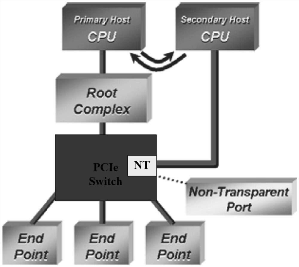
In order to carry out dynamic burn-in of the domestic N-port non-transparent bridge PCIe switching circuit in the production process at the actual operating frequency and interface rate, several CPUs including root complexes are provided to connect the upstream port and the NT port respectively according to typical application requirements, and several Endpoint devices are connected to the remaining downstream ports to provide burn-in incentives and output loads; however, in the mass production of circuits, N×M peripheral PCIe devices including the CPU need to be provided as incentives and loads for the burn-in of M circuits, resulting in The high cost of components and components seriously reduces the density of PCIe switching circuits on the single board, which brings high or even unacceptable test costs

Method used


Image

  • Dynamic aging device and method for non-transparent bridge PCIe switching circuit
  • Dynamic aging device and method for non-transparent bridge PCIe switching circuit
  • Dynamic aging device and method for non-transparent bridge PCIe switching circuit

Examples


Embodiment Construction

[0033] In order to make those skilled in the art better understand the solutions of the present invention, the technical solutions in the embodiments of the present invention will be clearly and completely described below with reference to the accompanying drawings in the embodiments of the present invention. Obviously, the described embodiments are only Embodiments are part of the present invention, but not all embodiments. Based on the embodiments of the present invention, all other embodiments obtained by persons of ordinary skill in the art without creative efforts shall fall within the protection scope of the present invention.

[0034]It should be noted that the terms "first", "second" and the like in the description and claims of the present invention and the above drawings are used to distinguish similar objects, and are not necessarily used to describe a specific sequence or sequence. It is to be understood that the data so used may be interchanged under appropriate c...


PUM


Abstract

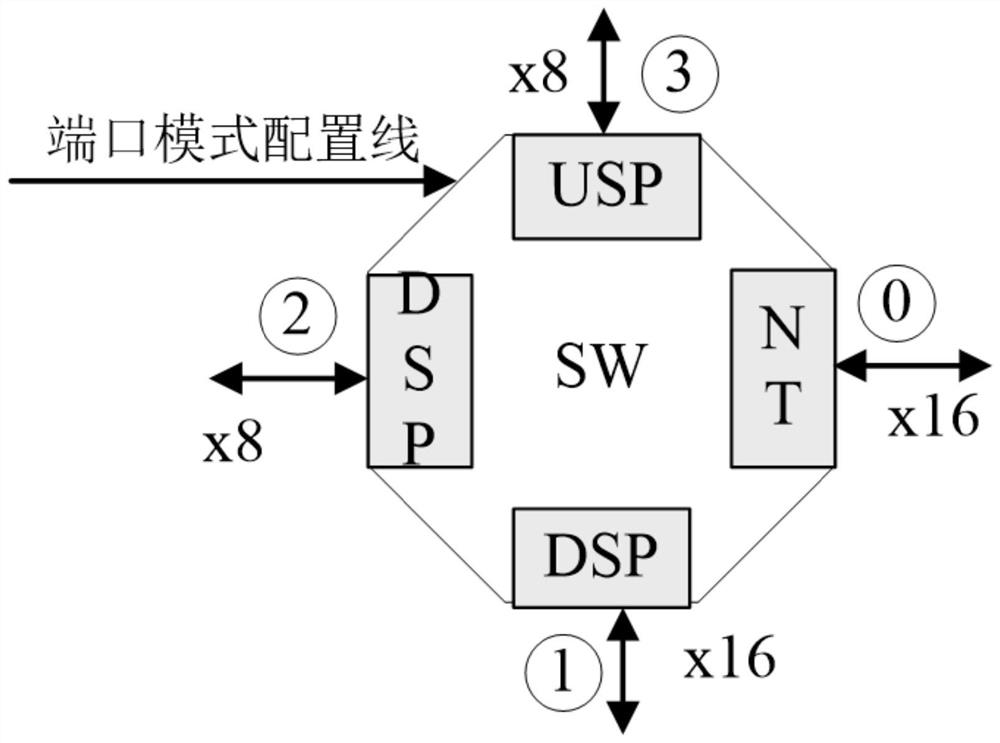
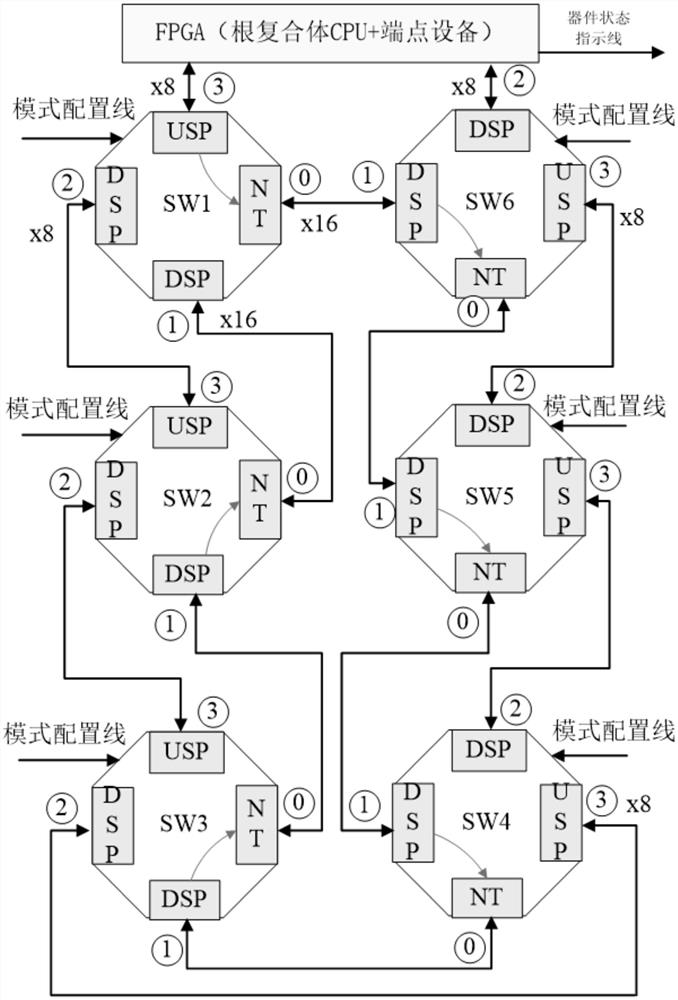
The invention discloses a dynamic aging device and method for a non-transparent bridge PCIe switching circuit, and the device employs a root complex CPU, an endpoint device, a port mode configuration line, a port interconnection bus, and a device state indication line, and covers a physical layer, a data link layer, a transaction layer, and a non-transparent bridge address conversion and switching function of the circuit. The circuit is dynamically aged according to the normal working frequency and the bus interface rate during the aging period; according to the invention, a root complex CPU and numerous PCIe endpoint devices do not need to be externally connected to each non-transparent bridge PCIe switching circuit, only one root complex CPU is needed on the whole burn-in board, and the cost of components on the burn-in board is greatly saved due to the connection mode of the root complex CPU; due to the fact that the number of peripheral PCIe devices is reduced, the density of aging devices on the aging board of the same area is increased, more circuits can be aged in the same aging high-temperature box, and the test cost is saved.

Description

technical field [0001] The invention belongs to the field of integrated circuit design and testing, and in particular relates to a dynamic aging device and method for a non-transparent (Non-Transparent, NT) bridge PCIe switching (Switch) circuit. Background technique [0002] High-reliability and high-quality integrated circuits are screened or eliminated through burn-in tests during the production process to ensure the reliability of the factory circuits. Without burn-in testing, these defective devices can experience incipient fatal failures or early life failures in service. In addition, some component users will also perform dynamic burn-in tests on purchased circuits to check the quality of the circuits in this batch. The dynamic burn-in test requires the test circuit to apply appropriate excitation and output load, so that the circuit is as close to the actual application as possible, and burns at the actual operating frequency and interface rate. [0003] In a PCIe ...

Claims


Application Information

Patent Timeline
Patent Type & Authority Applications(China)
IPC IPC(8): G01R31/28G01R1/04
CPCG01R31/2855G01R1/0433
Inventor 翟宝峰王蕊琪祁美娟董劭颖郝奎高宜楠王剑峰杨靓
Owner XIAN MICROELECTRONICS TECH INST
Why Eureka
Try Eureka