Plug-in box placing rack, energy storage rack and battery cluster

A technology for placing racks and inserting boxes, which is applied to battery pack parts, circuits, electrical components, etc. It can solve the problems of simple structure, low strength, and unfavorable stable placement of large battery inserting boxes, so as to achieve stable placement and improve support strength. Effect

Pending Publication Date: 2022-05-27
中创新航科技股份有限公司
View PDF0 Cites 0 Cited by
  • Summary
  • Abstract
  • Description
  • Claims
  • Application Information

AI Technical Summary

Problems solved by technology

[0002] The energy storage device is a new energy device that stores the battery box in the energy storage rack. Specifically, the battery box is placed on the box placement rack of the energy storage rack, and passes through the placement beam of t

Method used


Image

  • Plug-in box placing rack, energy storage rack and battery cluster
  • Plug-in box placing rack, energy storage rack and battery cluster
  • Plug-in box placing rack, energy storage rack and battery cluster

Examples


Example Embodiment

[0035] Example 1

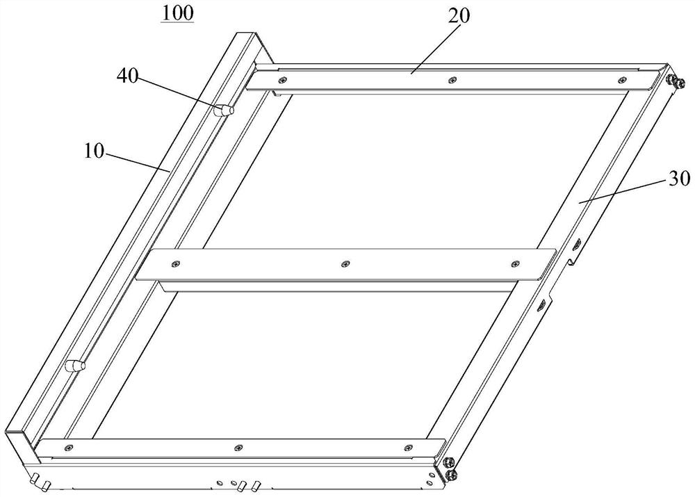
[0036] like figure 1 As shown, the present invention provides a subrack placement rack 100, which is used on the energy storage rack 200. The subrack placement rack 100 includes a first beam 10. Specifically, the subrack placement rack 100 includes the first beam 10, The two second beams 20 and the third beam 30, the first beam 10, the two second beams 20 and the third beam 30 are enclosed to form a rectangular frame structure, the third beam 30 and the first beam 10 are arranged opposite to each other, and the two The two beams 20 are arranged opposite to each other. Preferably, the structures of the two second beams 20 are the same, wherein:

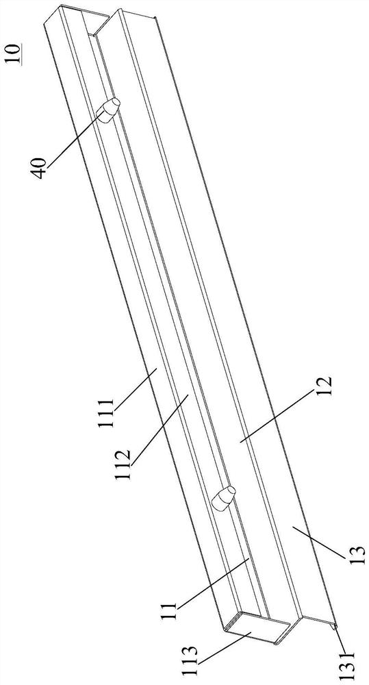
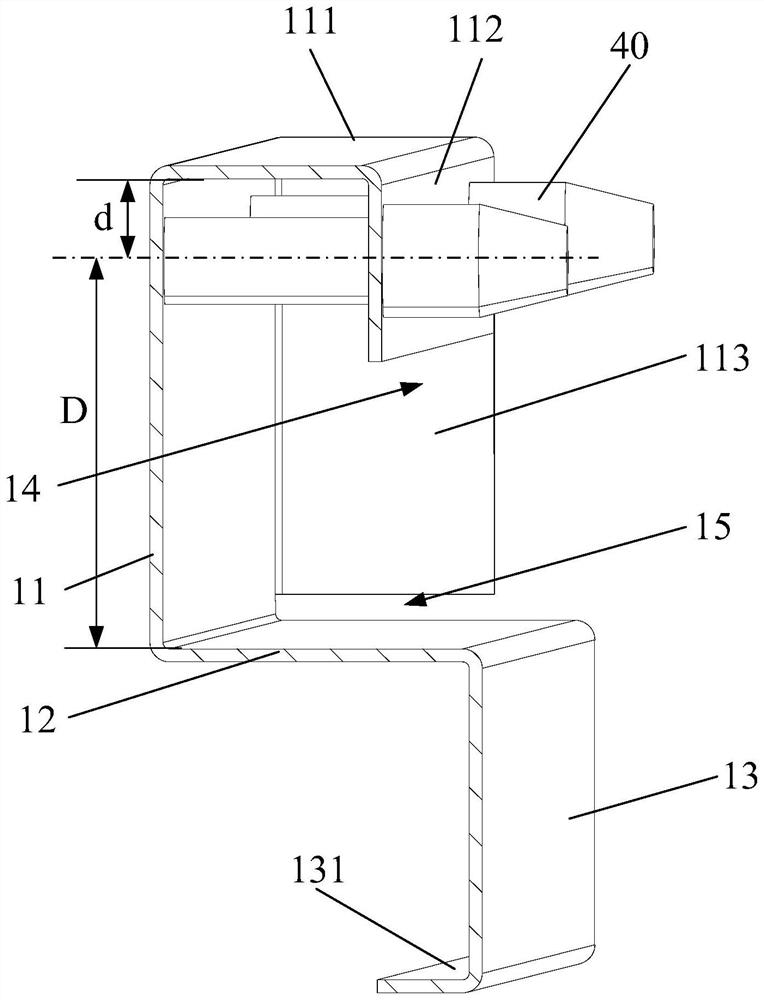
[0037] like figure 2 and image 3 As shown, the first beam 10 is formed by bending sheet metal, and the first beam 10 includes a limit plate 11, a support plate 12 and a reinforcement plate 13, that is, the limit plate 11, the support plate 12 and the reinforcement plate 13 are made of sheet metal The one-piece ...

Example Embodiment

[0052] Embodiment 2

[0053] like Figure 4 As shown, the present invention also provides an energy storage rack 200 , which includes the above-mentioned sub-box placement rack 100 . Specifically, the energy storage rack 200 includes a frame 201 , and the sub-box placement rack is installed in the frame 201 .

[0054] The energy storage rack of the present invention has the above-mentioned insertion box placement rack, so the energy storage rack has the advantage of being able to stably place large battery insertion boxes.

[0055] further, as Figure 4 As shown, the energy storage rack further includes uprights 2011. Specifically, the frame 201 includes uprights 2011, and the box placement rack 100 further includes a second beam 20. One end of the first beam 10 is connected to the second beam 20. The second beam 20 is connected with the upright post 2011 , that is, the box placement rack 100 is connected with the upright post 2011 through the second beam 20 .

[0056] Furt...

Example Embodiment

[0057] Embodiment 3

[0058] like Figure 5 As shown, the present invention also provides a battery cluster, which includes the above-mentioned energy storage rack 200 and at least one battery insertion box 300, the battery insertion box 300 is inserted in the energy storage rack 200, wherein the battery insertion box 300 The number of placements can be adjusted according to actual usage needs and the capacity of the energy storage rack 200 .

[0059] The battery cluster of the present invention has the above-mentioned energy storage rack, so it has the advantage of stable placement of a large battery box.

[0060] To sum up, in the box placement rack of the present invention, by setting the reinforcing plate, the supporting strength of the support plate can be improved, thereby ensuring that the battery box is stably placed on the box placement rack; by setting the limit plate, the battery The insertion box can be accurately installed in place, which avoids the suspension o...


PUM


Abstract

The invention provides a plug-in box placing rack, an energy storage rack and a battery cluster, the plug-in box placing rack comprises a first beam formed by bending a metal plate, the first beam comprises a limiting plate, a supporting plate and a reinforcing plate, the limiting plate and the reinforcing plate are connected to the two sides of the supporting plate respectively, the limiting plate is located above the supporting plate, the reinforcing plate is located below the supporting plate, and the limiting plate is located above the supporting plate. The supporting plate is configured to support the battery plug-in box, and the limiting plate is configured to abut against the battery plug-in box in the plug-in direction of the battery plug-in box. According to the plug-in box placing rack, the reinforcing plate is arranged, so that the supporting strength of the supporting plate can be improved, and therefore, it is ensured that a battery plug-in box is stably placed on the plug-in box placing rack; by arranging the limiting plates, the situation that the battery subrack is suspended in the placing process is avoided, and it is further guaranteed that the battery subrack is stably placed on the subrack placing frame. The energy storage rack provided by the invention is provided with the plug-in box placing rack, so that the energy storage rack has the advantage of being capable of stably placing the large-scale battery plug-in box.

Description

technical field [0001] The present invention relates to the technical field of batteries, in particular to a box placement rack and an energy storage rack. Background technique [0002] The energy storage device is a new energy device that stores the battery box in the energy storage rack. Specifically, the battery box is placed on the box placement rack of the energy storage rack, and passes through the placement beam of the box placement rack. However, the currently used placement beam has a simple structure, low strength, and is not conducive to assembly, so it is not conducive to the stable placement of a large battery insertion box. SUMMARY OF THE INVENTION [0003] An object of the present invention is to provide a box placement rack with high beam strength, so as to facilitate stable placement of large battery boxes. [0004] In order to achieve the above object, the present invention provides a box placement rack, which includes a first beam formed by bending shee...

Claims


Application Information

Patent Timeline
IPC IPC(8): H01M50/244
CPCH01M50/244Y02E60/10H01M50/251H01M50/262H01M50/224H01M50/291H01M50/204H01M2220/10
Inventor 李炜石腾腾李菲
Owner 中创新航科技股份有限公司
Why Eureka
Try Eureka