Energy storage system

An energy storage system and energy technology, applied in the field of energy storage systems, can solve problems such as increased heating power consumption of the battery heating circuit, damage to the battery heating circuit, unfavorable selection of electrical components in the battery heating circuit, etc., to prolong the service life, Easy selection and controllable power supply voltage

Pending Publication Date: 2022-05-27
SUNGROW POWER SUPPLY CO LTD
View PDF0 Cites 0 Cited by
  • Summary
  • Abstract
  • Description
  • Claims
  • Application Information

AI Technical Summary

Problems solved by technology

However, the power supply voltage obtained by the battery heating circuit from the AC power grid is not controlled. In practical applications, users are prone to connect the power supply voltage of the battery heating circuit from the AC phase voltage to the line voltage, resulting in heating of the battery heating circuit. The power consumption increases sharply. For example, when the phase voltage is 230V, the line voltage is 400V, and the heating resistance in the battery heating circuit is 200Ω, the heating power consumption of the battery heating circuit is 264.5W at the phase voltage, and the heating power of the battery heating circuit at the line voltage is 264.5W. The power consumption is 800W, and the difference between the two situations is nearly 3 times, which not only easily leads to damage to the battery heating circuit, but also is not conducive to the selection of electrical components in the battery heating circuit

Method used


Image

  • Energy storage system
  • Energy storage system
  • Energy storage system

Examples


Embodiment Construction

[0039] The technical solutions in the embodiments of the present invention will be clearly and completely described below with reference to the accompanying drawings in the embodiments of the present invention. Obviously, the described embodiments are only a part of the embodiments of the present invention, rather than all the embodiments. Based on the embodiments of the present invention, all other embodiments obtained by those of ordinary skill in the art without creative efforts shall fall within the protection scope of the present invention.

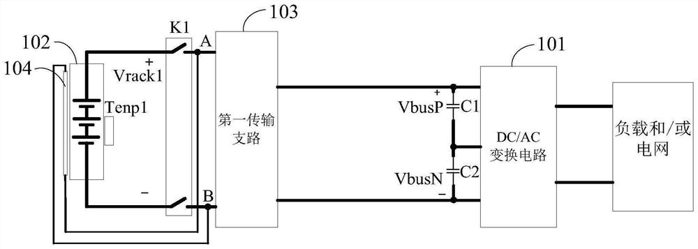
[0040] An embodiment of the present invention discloses an energy storage system, comprising: a controller, a DC / AC conversion circuit, at least one battery unit and a corresponding first transmission branch, a battery heating circuit, and a number of first switches equal to the battery units, Each battery unit is connected to the DC bus of the DC / AC conversion circuit through the corresponding first switch and the first transmission ...


PUM


Abstract

The invention discloses an energy storage system, which comprises a controller, a DC / AC conversion circuit, at least one battery unit and a corresponding first transmission branch, a battery heating circuit and a first switch, and is characterized in that each battery unit is connected with a DC bus of the DC / AC conversion circuit through the corresponding first switch and the first transmission branch in sequence; the power supply ends of the battery heating circuits are connected between the first switches and the corresponding first transmission branches, and when the temperature of at least one battery unit is lower than a preset temperature value, the controller controls the corresponding first transmission branches to boost or reduce the voltage of the direct-current bus according to the voltage of the direct-current bus so as to supply power to the corresponding battery heating circuits. Therefore, the corresponding battery unit is heated. The power supply voltage of the battery heating circuit is the direct-current bus voltage, so that the condition of wrong connection of phase voltage and line voltage does not exist, the service life of the battery heating circuit is prolonged, and model selection of electrical elements is facilitated.

Description

technical field [0001] The invention relates to the technical field of power electronics, and more particularly, to an energy storage system. Background technique [0002] The storage and conversion of clean energy is of great significance to solving global warming. Lithium-ion batteries have been widely studied and focus on. [0003] However, the external characteristics of lithium-ion power batteries are easily affected by ambient temperature, especially in low temperature environments, their capacity is reduced, and low temperature charging is not only unsatisfactory, but also causes damage to the battery, reducing battery life and battery life. effective capacity. Therefore, in a low temperature environment, before the battery is used, it needs to be preheated to make the inner core of the battery reach the normal operating temperature range. [0004] In the traditional battery preheating method, electricity is generally taken from the AC grid to supply power to the b...

Claims


Application Information

Patent Timeline
IPC IPC(8): H02J3/38H02M7/44H02M3/04H01M10/615H01M10/657
CPCH02J3/381H02M7/44H02M3/04H01M10/615H01M10/657H02J2300/22Y02E60/10
Inventor 耿后来曹伟孙维李鹏举
Owner SUNGROW POWER SUPPLY CO LTD
Why Eureka
Try Eureka