Combined diesel motor rotor workpiece and assembling method thereof

A motor rotor and combined technology, applied in the direction of electromechanical devices, electrical components, electric components, etc., can solve the problems of unfavorable automatic assembly, loose locking ring, etc., and achieve the effect of reasonable structural design and easy disassembly and replacement

Pending Publication Date: 2022-05-27
CHANGZHOU SHENLI MOTOR
View PDF1 Cites 1 Cited by
  • Summary
  • Abstract
  • Description
  • Claims
  • Application Information

AI Technical Summary

Problems solved by technology

[0004] However, this segmented motor rotor core still has disadvantages when it is used. First, the direction of rotation of the thread groove is the same as the working direction of the rotating shaft, which will easily lead to loosening of the locking ring for a long time; second, it is not conducive to automatic assembly.

Method used


Image

  • Combined diesel motor rotor workpiece and assembling method thereof
  • Combined diesel motor rotor workpiece and assembling method thereof
  • Combined diesel motor rotor workpiece and assembling method thereof

Examples


Embodiment 1

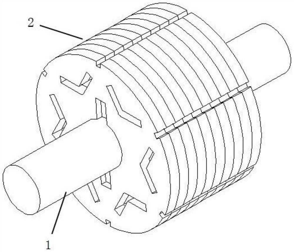
[0035] like Figure 1-Figure 6 As shown, this embodiment is a combined diesel motor rotor workpiece, including a rotating shaft 1 and a combined rotor core 2:

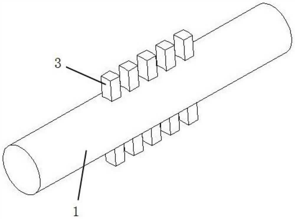
[0036] In this embodiment, a plurality of pegs 3 are arranged on the rotating shaft 1 side by side, and the rotating shaft 1 and the pegs 3 are integrally formed.

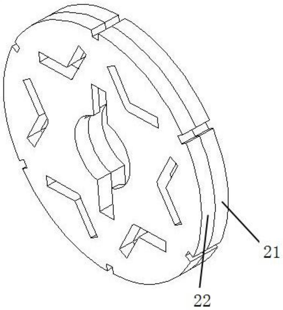
[0037] In this embodiment, the combined rotor core 2 is composed of several groups of splicing blocks arranged side by side, and each group of splicing blocks is formed by butting a splicing block I 21 and a splicing block II 22 with symmetrical structures. The splicing block I 21 and the splicing block II 22 each include a sheet body 211 , and the sheet body 211 is provided with a central through hole 212 , an introduction hole 213 , a movable slot 214 , a permanent magnet mounting hole 215 and a welding slot 216 . The center of the sheet body 211 is provided with a central through hole 212, the introduction hole 213 and the movable slot 214 are symmetric...

Embodiment 2

[0047] The structure of the present embodiment is basically the same as that of the first embodiment, the difference lies in that the rotating shaft and the dial column are of separate structures, and the rotating shaft is provided with sockets for inserting the dial column side by side.

Embodiment 3

[0049] The structure of this embodiment is basically the same as that of the first embodiment, and the difference lies in that the central angle of the movable groove is 45 degrees.


PUM


Abstract

The invention belongs to the technical field of motor production and processing, and particularly relates to a combined diesel motor rotor workpiece and an assembling method thereof. The combined rotor core is composed of a plurality of groups of splicing blocks which are arranged side by side, each group of splicing blocks is formed by butting a splicing block I and a splicing block II which are symmetrical in structure, each of the splicing blocks I and the splicing block II comprises a sheet body, and a central through hole, a lead-in hole, a movable groove, a permanent magnet mounting hole and a welding groove are formed in each sheet body; during assembly, the combined rotor iron core is formed by welding firstly, then the combined rotor iron core is sleeved in the rotating shaft, and the shifting column on the rotating shaft enters the lead-in hole and then rotates into the movable groove, so that the assembly can be completed. The rotor workpiece provided by the invention is reasonable in structural design, can be assembled through staggered clamping, does not need to be provided with a thread locking and anchoring locking structure, and is beneficial to assembly and later disassembly and replacement.

Description

technical field [0001] The invention belongs to the technical field of motor production and processing, and particularly relates to a combined diesel motor rotor workpiece and an assembling method thereof. Background technique [0002] The rotor iron core is a punched lamination structure. At present, in order to improve the mechanical strength of the rotor iron core, the rotor iron core will be fastened together by means of rivets after lamination. For longer diesel generators, the length of the rotor iron core used will also be longer, and the current lamination process is difficult to laminate the rotor iron core into an integral type, so the rotor iron core generally adopts a segmented design . The rotor core of the traditional segmented motor is fastened by rivets for each segment, so there will be a gap between the two adjacent rotor cores, and the length of this gap is the length of the ineffective electromagnetic action, which eventually leads to an increase in the ...

Claims


Application Information

Patent Timeline
Patent Type & Authority Applications(China)
IPC IPC(8): H02K1/30H02K1/274H02K15/02H02K15/03
CPCH02K1/30H02K1/274H02K15/02H02K15/03
Inventor 陈猛张兵赵恒
Owner CHANGZHOU SHENLI MOTOR
Why Eureka
Try Eureka