Hybrid core driving device and forming machine

A driving device and hybrid technology, applied in the direction of core, mold composition, mold, etc., can solve the problems of difficulty in shortening the operation cycle time of the die-casting machine and the inability to open and close the fixed mold and the movable mold at the same time. The effect of shortening the work cycle time, simplifying the equipment, and suppressing the deterioration of the work environment

Active Publication Date: 2022-05-27
SHIBAURA MASCH CO LTD
View PDF6 Cites 0 Cited by
  • Summary
  • Abstract
  • Description
  • Claims
  • Application Information

AI Technical Summary

Problems solved by technology

In the case of a common hydraulic circuit, the opening and closing of the fixed mold and the movable mold and the movement of the core cannot be performed at the same time, and it is difficult to shorten the operation cycle time of the die casting machine

Method used


Image

  • Hybrid core driving device and forming machine
  • Hybrid core driving device and forming machine
  • Hybrid core driving device and forming machine

Examples


no. 1 Embodiment approach

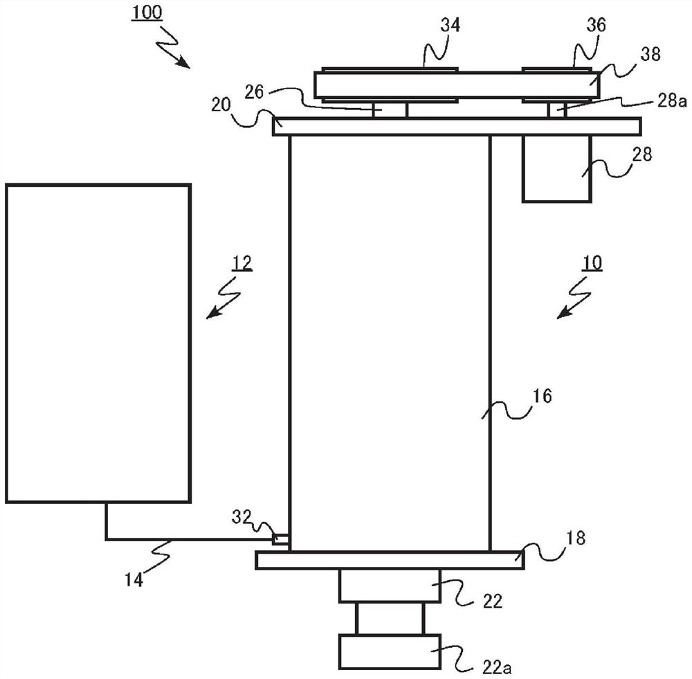
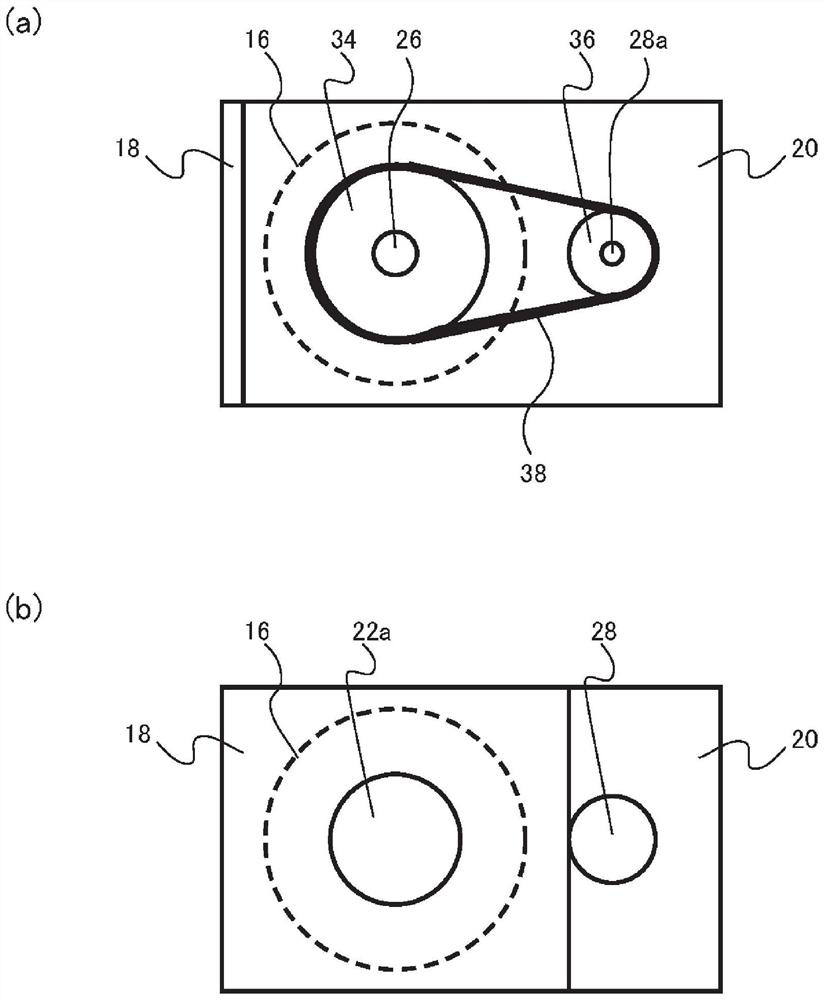
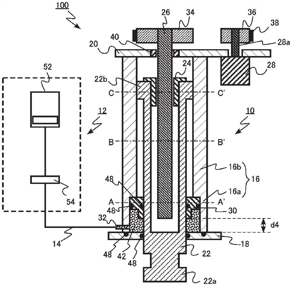
[0053] The hybrid core drive device according to the first embodiment includes a cylinder tube; a first cover member fixed to one end of the cylinder tube; a second cover member fixed to the other end of the cylinder tube; In the cylinder tube, the core can be connected at one end; the rod has an annular flange on the side of the second cover member rather than the connecting part, penetrates the first cover member, and can move linearly forward and backward relative to the cylinder tube; nut , fixed on the rod; the screw shaft, which penetrates the second cover member and the nut, is arranged to be inserted into the rod, and can rotate; the motor rotates the screw shaft; the annular piston is arranged in the cylinder, The rod penetrates the rod so as to be slidable with respect to the cylinder tube and the rod, and a connecting portion is provided on the cylinder tube and can be connected to a pipe for supplying a working fluid for operating the piston to an area surrounded by...

no. 2 Embodiment approach

[0124] The molding machine according to the second embodiment includes: a base; a fixed die plate that is fixed on the base and holds the fixed die; and a movable die plate that is movably installed on the base in the die opening and closing direction, and aligns the movable die and the fixed die. Set and hold; Hybrid core drive device, drive the core combined with the fixed mold and movable mold; Clamping device, close the fixed mold and movable mold; Injection device, to the fixed mold, movable mold and mold The cavity formed by the core is filled with molten material; and the control unit controls the operation of the hybrid core drive device; the hybrid core drive device includes: a cylinder; a first cover member fixed to one end of the cylinder; a second The cover member is fixed to the other end of the cylinder tube; the rod, at least a part of which is provided in the cylinder tube, has a connecting portion at one end capable of connecting the core, and has an annular fl...


PUM


Abstract

A hybrid core drive device according to an embodiment is provided with: a cylinder tube; a first cover member at one end of the cylinder tube; a second cover member at the other end; a rod which has a connection part to which the core is connected at one end of the cylinder tube, has an annular flange on the second cover member side, and penetrates the first cover member; the nut is fixed on the rod; a screw shaft penetrating the second cover member and the nut and provided so as to be insertable into the rod; a motor that rotates the screw shaft; a piston which is provided in the cylinder tube, through which the rod passes, and which is capable of sliding relative to the cylinder tube and the rod; and a connection part capable of connecting a pipe for supplying the operating fluid to a region surrounded by the cylinder tube, the first cover member, and the piston.

Description

technical field [0001] The present invention relates to a core driving device and a molding machine used when a mold having a core is used to manufacture a product. Background technique [0002] A die casting machine, which is an example of a molding machine, produces a product (die casting) by filling a cavity (cavity) in a mold clamped with a mold clamping device with a molten metal using an injection device. When a product has an undercut in the mold opening and closing direction, a mold having a core is used in addition to the fixed mold and the movable mold. [0003] When a mold having a core is used, a core driving device is provided for inserting the core into the stationary mold or the movable mold and for pulling the core out of the stationary mold or the movable mold. When pulling out the core from the stationary mold or the movable mold, a large driving force is required for the core driving device in order to pull the core away from the product. In addition, af...

Claims


Application Information

Patent Timeline
Patent Type & Authority Applications(China)
IPC IPC(8): B22D17/22B22D17/24
CPCB22D17/2236B22D17/24B22C9/108B22D17/32B29C45/36B29C45/68B29C2045/363B29C2045/686
Inventor 内藤光俊辻真野田三郎
Owner SHIBAURA MASCH CO LTD
Why Eureka
Try Eureka