Eureka AIR delivers breakthrough ideas for toughest innovation challenges, trusted by R&D personnel around the world.

Lifting device and foot massage electric appliance

A lifting device and lifting component technology, applied in bathing devices, vehicle parts, electric vehicles, etc., can solve problems such as inability to automatically fold

Inactive Publication Date: 2022-05-31
佛山市星曼信息科技有限公司
View PDF0 Cites 0 Cited by
  • Summary
  • Abstract
  • Description
  • Claims
  • Application Information

AI Technical Summary

Problems solved by technology

[0004] Based on this, it is necessary to provide a lifting device and a massage appliance to solve the problem that automatic folding cannot be performed.

Method used


Image

  • Lifting device and foot massage electric appliance
  • Lifting device and foot massage electric appliance
  • Lifting device and foot massage electric appliance

Examples


Embodiment 1

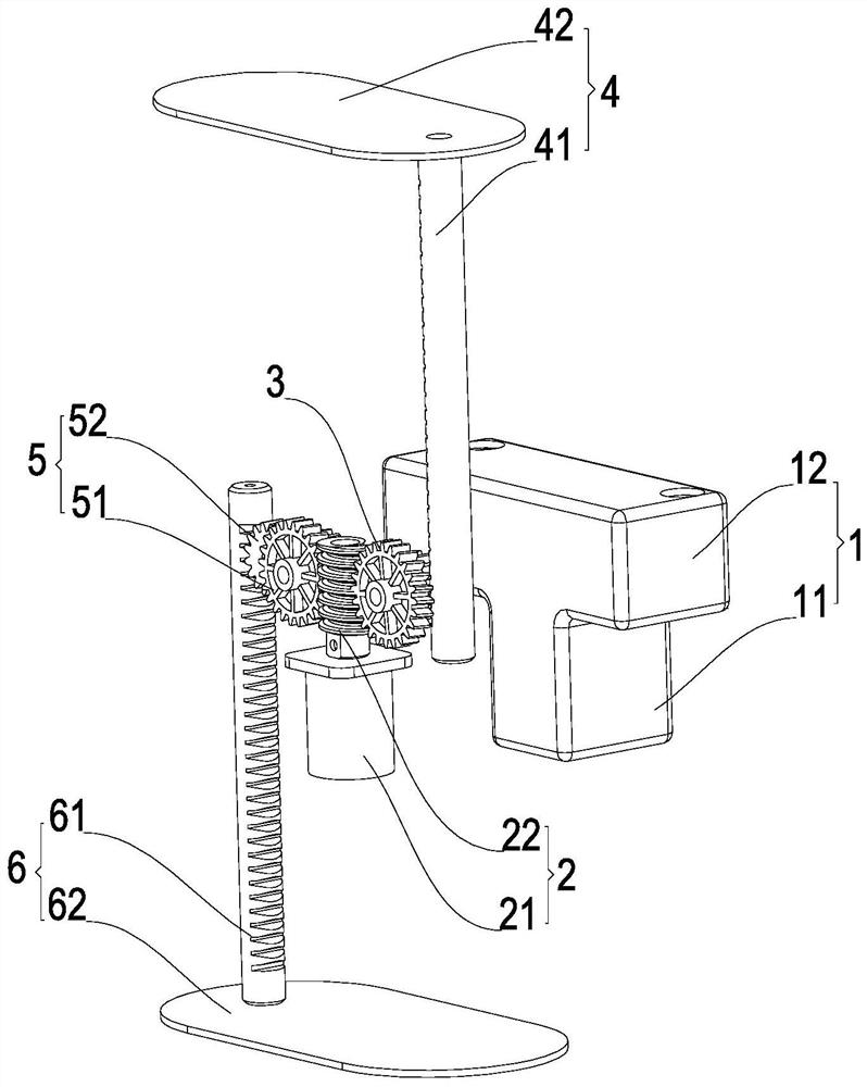
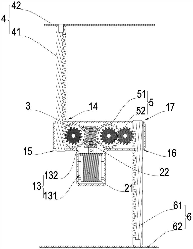
[0049] Such as Figure 1 ~ Figure 4 As shown, this embodiment discloses a lifting device, comprising: a first lifting assembly 4 and a second lifting assembly 6, wherein at least one of the first lifting assembly 4 and the second lifting assembly 6 is a lifting rack; the driving device 2 , the driving device 2 drives the first lifting assembly 4 to move to raise or lower the first stroke, the driving device 2 drives the second lifting assembly 6 to move to raise or lower the second stroke, the first stroke and the second stroke The sum is the total raised or lowered height of the lift.

[0050] The present invention provides a lifting device to drive the first lifting assembly 4 and the second lifting assembly 6 to work when the driving device 2 is working, and when the first lifting assembly 4 is working, the first lifting assembly 4 is first driven by the driving device 2 The movement causes the first lifting assembly 4 to move away from or close to the driving device 2 in ...

Embodiment 2

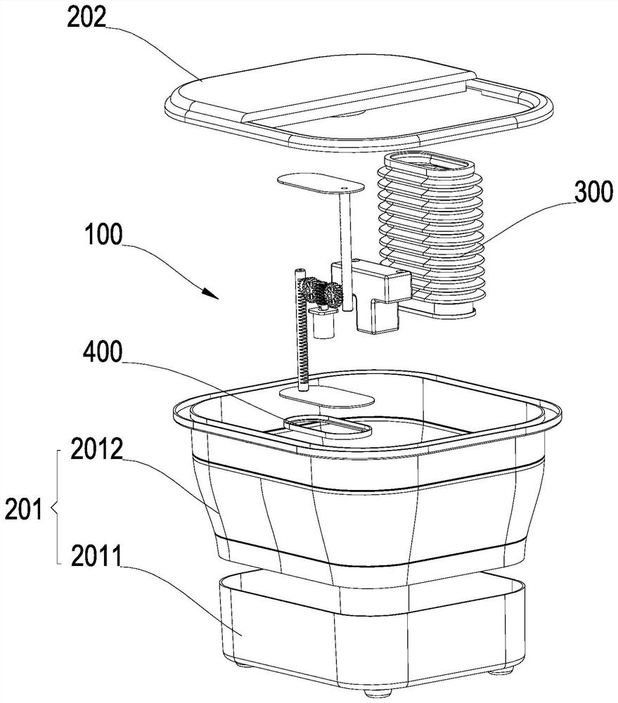
[0067] Such as Figure 1 ~ Figure 4 As shown, the second aspect of the present invention provides a foot massage electrical appliance, specifically a foot bath, and the foot bath includes: a basin assembly 200, which is at least partially foldable and has a folded state and an open state; and the above-mentioned lift In the device 100, one of the first lifting assembly 4 and the second lifting assembly 6 is connected to the upper end of the basin assembly 200, and the other is connected to the lower end of the basin assembly 200; the first lifting assembly 4 and the second lifting assembly 6 are respectively facing When moving away from the installation shell 1, the basin assembly 200 is opened, and when the first lifting assembly 4 and the second lifting assembly 6 move toward the direction close to the installation shell 1, the basin assembly 200 is folded; the control device controls The device is electrically connected with the driving device.

[0068] A massage electric ...


PUM


Abstract

The invention relates to a lifting device and a massage electric appliance. The lifting device comprises a mounting shell; the driving device is arranged on the mounting shell; the first transmission part is arranged on the mounting shell; the first lifting assembly is arranged on the mounting shell, and when the first transmission part moves, the first lifting assembly can be driven to move in the first direction away from the mounting shell or move in the direction close to the mounting shell; the second transmission part is arranged on the mounting shell, and the driving device is used for driving the second transmission part and the first transmission part to move; and the second lifting assembly is arranged on the mounting shell, when the second transmission part moves, the second lifting assembly can be driven to move in the second direction away from the mounting shell or move in the direction close to the mounting shell, and the second direction is opposite to the first direction.

Description

technical field [0001] The invention relates to the field of massage electric appliances, in particular to a lifting device and a massage electric appliance. Background technique [0002] A massage appliance used for foot washing and massage. The foot is one of the places where the meridians of the human body converge. Each organ in the human body has a specific reflection area on the foot. The reflection area is the focal point of the nerves, and each point is related to a certain organ of the body. , using mechanical and physical methods to stimulate these reflex areas, so that blood circulation in the reflex areas and related organs of the body can be accelerated, the balance of the body can be adjusted, the tension of the whole body can be relieved, the effect of disease prevention can be achieved, and the effect of self-care and longevity can be achieved. With the improvement of living standards, massage appliances have become a very popular way of health care in the ma...

Claims


Application Information

Patent Timeline
Patent Type & Authority Applications(China)
IPC IPC(8): A61H35/00
CPCA61H35/006A61H2201/1215A61H2201/14A61H2201/0169A61H2201/0161Y02T10/7072
Inventor 欧阳杰鹏肖移龙莫润超谢慧皇
Owner 佛山市星曼信息科技有限公司
Why Eureka
Eureka Blog
Learn More