
Shaft machining, polishing and detecting device

A detection device and shaft technology, applied in the field of workpiece processing, can solve the problems of time-consuming and laborious, reduce the practicability of grinding devices, increase costs, etc., and achieve the effect of ensuring a clean environment

Pending Publication Date: 2022-05-31
DALIAN DEMAISHI PRECISION TECH CO LTD
View PDF0 Cites 1 Cited by
  • Summary
  • Abstract
  • Description
  • Claims
  • Application Information

AI Technical Summary

Problems solved by technology

[0004] The purpose of the present invention is to solve the problem that the clamping and fixing structure in the prior art is relatively simple, and the size of the shaft cannot be adjusted according to the size of the shaft, thereby reducing the practicability of the grinding device, and lack of detection of the overall surface flatness of the shaft. As a result, after the surface of the shaft is polished, it needs to be manually or transferred to another device for inspection, which not only takes time and effort, but also increases the cost, thereby reducing the work efficiency. Processing and grinding detection device

Method used


Image

  • Shaft machining, polishing and detecting device
  • Shaft machining, polishing and detecting device
  • Shaft machining, polishing and detecting device

Examples


Embodiment 1

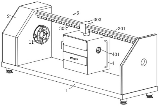
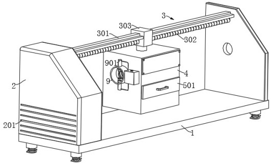
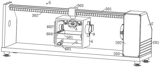
[0037] Embodiment 1: refer to Figure 1-11, a shaft processing and grinding detection device, including a bottom plate 1, also includes: a processing box 4 arranged on the bottom plate 1, a chassis 2, a conveying mechanism 3 for driving the processing box 4 to move, and the outer walls of both sides of the processing box 4 are Be provided with feed inlet 401, be provided with hairbrush 403 in feed inlet 401, wherein, processing box 4 top inner wall is provided with and is used for the grinding mechanism that shaft class is polished; The outer wall of the processing box 4; the piston cylinder 901 is fixedly connected to the collar one 9; the piston disk 902 is slidably connected in the piston cylinder 901, and the piston disk 902 is fixedly connected with a guide rod 903; the limit sleeve 905 is fixedly connected On the top of the guide rod 903, a universal ball 906 is slidably connected in the limit sleeve 905; the water nozzle 909 is fixedly connected to the inner wall of the...

Embodiment 2

[0050] Embodiment 2: refer to Figure 5 , Figure 11 , a shaft processing and grinding detection device, including a bottom plate 1, also includes: a processing box 4 arranged on the bottom plate 1, a chassis 2, a conveying mechanism 3 for driving the processing box 4 to move, and the outer walls of both sides of the processing box 4 are Be provided with feed inlet 401, be provided with hairbrush 403 in feed inlet 401, wherein, processing box 4 top inner wall is provided with and is used for the grinding mechanism that shaft class is polished; The outer wall of the processing box 4; the piston cylinder 901 is fixedly connected to the collar one 9; the piston disk 902 is slidably connected in the piston cylinder 901, and the piston disk 902 is fixedly connected with a guide rod 903; the limit sleeve 905 is fixedly connected On the top of the guide rod 903, a universal ball 906 is slidably connected in the limit sleeve 905; the water nozzle 909 is fixedly connected to the inner...

Embodiment 3

[0056] Embodiment 3: refer to Figure 11, a shaft processing and grinding detection device, including a bottom plate 1, also includes: a processing box 4 arranged on the bottom plate 1, a chassis 2, a conveying mechanism 3 for driving the processing box 4 to move, and the outer walls of both sides of the processing box 4 are Be provided with feed inlet 401, be provided with hairbrush 403 in feed inlet 401, wherein, processing box 4 top inner wall is provided with and is used for the grinding mechanism that shaft class is polished; The outer wall of the processing box 4; the piston cylinder 901 is fixedly connected to the collar one 9; the piston disk 902 is slidably connected in the piston cylinder 901, and the piston disk 902 is fixedly connected with a guide rod 903; the limit sleeve 905 is fixedly connected On the top of the guide rod 903, a universal ball 906 is slidably connected in the limit sleeve 905; the water nozzle 909 is fixedly connected to the inner wall of the l...


PUM


Abstract

The invention discloses a shaft machining, polishing and detecting device, and belongs to the technical field of workpiece machining. The shaft machining, polishing and detecting device comprises a bottom plate and further comprises a machining box arranged on the bottom plate, a machine box and a conveying mechanism used for driving the machining box to move, feeding ports are formed in the outer walls of the two sides of the machining box, brushes are arranged in the feeding ports, and the conveying mechanism is arranged on the machine box. A grinding mechanism used for grinding the shafts is arranged on the inner wall of the top of the machining box. The lantern ring I and the water storage tank are fixedly connected to the outer wall of the processing box; according to the shaft polishing device, when a shaft is polished, four sets of clamping plates can be driven to correspondingly extend or retract in a third lantern ring through a telescopic clamping cylinder, then the shafts of different specifications and sizes can be clamped and limited conveniently, and after polishing is completed, the flatness of the overall surface of the shaft can be detected; and the protruding part of the outer surface of the shaft can be marked in the detection process.

Description

technical field [0001] The invention relates to the technical field of workpiece processing, in particular to a shaft processing and grinding detection device. Background technique [0002] The rotating shaft, as the name implies, is the shaft that must be used to connect the main parts of the product and is used to bear both bending moment and torque in the rotating work. Usually, the staff needs to grind the rotating shaft, and the staff will use the grinding device at this time. [0003] At present, the existing shaft processing and grinding device adopts a simple clamping and fixing structure, which cannot be adjusted according to the size of the shaft, thereby reducing the practicability of the grinding device and lacking the overall surface smoothness of the shaft. Inspection results in that after the shaft surface is polished, it needs to be manually or transferred to another device for inspection, which is not only time-consuming and laborious, but also increases cos...

Claims


Application Information

Patent Timeline
IPC IPC(8): B24B5/36B24B5/35B24B41/06B24B41/00B24B55/06G01B5/28
CPCB24B5/36B24B5/35B24B41/06B24B41/00B24B55/06G01B5/28Y02P70/10
Inventor 何建平
Owner DALIAN DEMAISHI PRECISION TECH CO LTD
Learn More