
Solid waste conveying device

A conveying device and conveyor belt technology, which is applied in the direction of conveyors, conveyor objects, transportation and packaging, etc., can solve the problems of odor overflow, inability to achieve full sealing, material leakage, etc., and achieve space saving, good air tightness, and reasonable The effect of using

Pending Publication Date: 2022-05-31
冀东水泥重庆合川有限责任公司
View PDF0 Cites 0 Cited by
  • Summary
  • Abstract
  • Description
  • Claims
  • Application Information

AI Technical Summary

Problems solved by technology

[0003] The conveying equipment commonly used in the solid waste disposal system in the prior art includes seal plate feeders, belt conveyors and bucket elevators, etc. Such equipment cannot achieve full sealing when conveying general solid waste such as polluted soil and dry sludge. There are odor overflow and material leakage, and there are certain risks in occupational health and environmental protection

Method used


Image

  • Solid waste conveying device
  • Solid waste conveying device
  • Solid waste conveying device

Examples


Embodiment 1

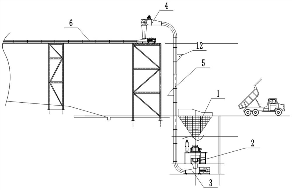
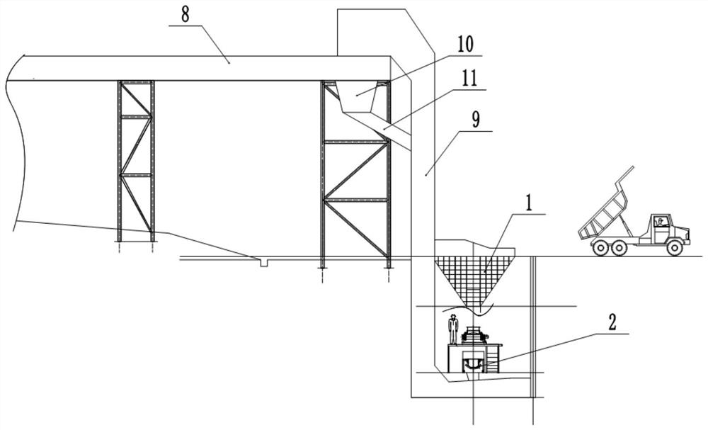
[0035] The embodiment is basically as attached figure 1 with figure 2 Shown: a solid waste conveying device, including a conveying belt 5, a conveying track and a driving unit, the conveying track is Z-shaped, the driving unit drives the conveying belt 5 to convey along the Z-shaped conveying track, and a lifting bucket 12 is connected to the conveying track. The solid waste conveying device in this embodiment further includes a first housing 9 , and both the conveying belt 5 and the conveying track are located in the first housing 9 .

[0036] Conveyor belt 5 comprises vertical section and two horizontal sections, and two horizontal sections are positioned at the top end and the bottom of vertical section respectively, and conveyer belt 5 has two turnings greater than or equal to 90 ° in the present embodiment, and conveyer belt 5 The horizontal section below is the feed end 3 , the horizontal section above the conveyor belt 5 is the discharge end 4 , and a belt conveyor 6 ...

Embodiment 2

[0049] Such as Figure 5 As shown, a solid waste conveying device differs from Embodiment 1 in that: the material guide box 11 in this embodiment is in a spiral shape, and the end of the material guide box 11 away from the collecting hopper 10 faces the conveyor belt 5 to lift the material. side.

[0050] In this embodiment, the spiral material guide box 11 can prolong the falling path of the material, thereby slowing down the falling speed of the material, and preventing the material from falling too fast to be conveyed by the lifting bucket 12 . In addition, in this embodiment, the material guide box 11 is in a spiral shape, which can change the direction in which the material falls, so that the material can fall to the side where the material is lifted by the conveyor belt 5, so that it is convenient to directly fall to the lifting machine that is located in the vertical section and is being transported upwards. In the bucket 12, it is convenient to directly transport the ...


PUM


Abstract

The invention relates to the technical field of conveying equipment, and discloses a solid waste conveying device which comprises a conveying belt, a conveying track and a driving unit, the conveying track is in a Z shape, the driving unit drives the conveying belt to convey along the conveying track in a Z shape, and the conveying track is connected with a lifting hopper; the conveying device further comprises a first shell, and the conveying belt and the conveying rail are both located in the first shell. The whole machine adopts a totally-closed structure, the air tightness is good, and the phenomena of ash leakage and peculiar smell overflow in the conveying process are avoided.

Description

technical field [0001] The invention relates to the technical field of conveying equipment, in particular to a solid waste conveying device. Background technique [0002] The current solid waste materials mainly include dry sludge, polluted soil, light materials, and plastic stool materials. Most of the materials contain toxic and harmful gases. Direct inhalation of the gas will endanger human health. Meet the airtight delivery. Thereby reducing the direct contact of employees with solid waste materials. [0003] The conveying equipment commonly used in the solid waste disposal system in the prior art includes seal plate feeders, belt conveyors and bucket elevators, etc. Such equipment cannot achieve full sealing when conveying general solid waste such as polluted soil and dry sludge. There are odor overflow and material leakage, and there are certain risks in occupational health and environmental protection. Contents of the invention [0004] The present invention inte...

Claims


Application Information

Patent Timeline
Patent Type & Authority Applications(China)
IPC IPC(8): B65G15/30B65G47/44B65G17/12B65G47/18
CPCB65G15/30B65G47/44B65G17/126B65G47/18Y02W30/62
Inventor 于俊杰马利民田文龙李明凯杨虎鲁鹏程
Owner 冀东水泥重庆合川有限责任公司
Learn More