
Cast-in-place concrete blocking method for beam-column joint part

A technology of beam-column joints and concrete, which is applied to the processing of building materials, construction, building reinforcements, etc., can solve problems such as quality defects, inconvenient construction, lack of lateral extrusion, etc., and achieve reliable blocking effect, simple and convenient construction, The effect of solving quality problems

Pending Publication Date: 2022-05-31
SHANDONG SANJIAN CONSTR ENG MANAGEMENT +1
View PDF0 Cites 0 Cited by
  • Summary
  • Abstract
  • Description
  • Claims
  • Application Information

AI Technical Summary

Problems solved by technology

Both of the above two cast-in-place concrete blocking methods have certain technical and quality problems: the first blocking method is inconvenient in construction (when the steel wire mesh is bound in the steel skeleton, for the binding point located at the bottom part of the steel skeleton, the construction personnel It is often impossible to bind effectively, and sometimes it is even impossible to reach and cannot be bound, resulting in lax blockage when pouring concrete), when tying pieces of steel mesh, the steel mesh is not tightly bound due to the structural steel bars passing through the steel skeleton, and the binding The steel wire mesh is easy to be washed away by the cast-in-place concrete, which leads to the phenomenon that the cast-in-place concrete is not tightly blocked, resulting in quality defects; when the second blocking method is constructed, there are problems such as the difficulty of fixing the wood, the lax blocking, and the poor quality of the concrete after pouring. The wood is not easy to pull out and other problems, resulting in concrete quality defects; and the above two blocking methods have the defect that the concrete blocking effect is not ideal due to the lack of lateral extrusion during concrete pouring

Method used


Image

  • Cast-in-place concrete blocking method for beam-column joint part
  • Cast-in-place concrete blocking method for beam-column joint part
  • Cast-in-place concrete blocking method for beam-column joint part

Examples


Embodiment Construction

[0026] The present invention will be further described below in conjunction with accompanying drawing by non-limiting embodiment:

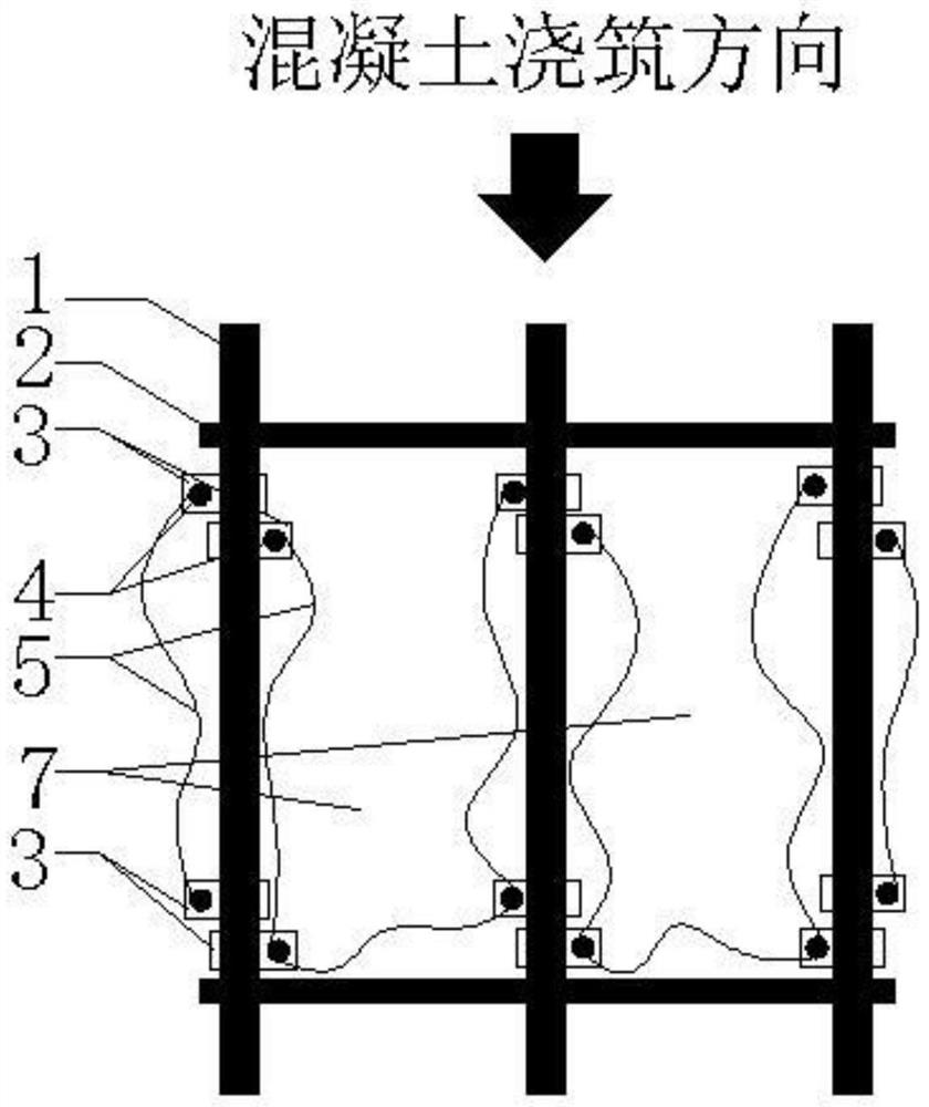
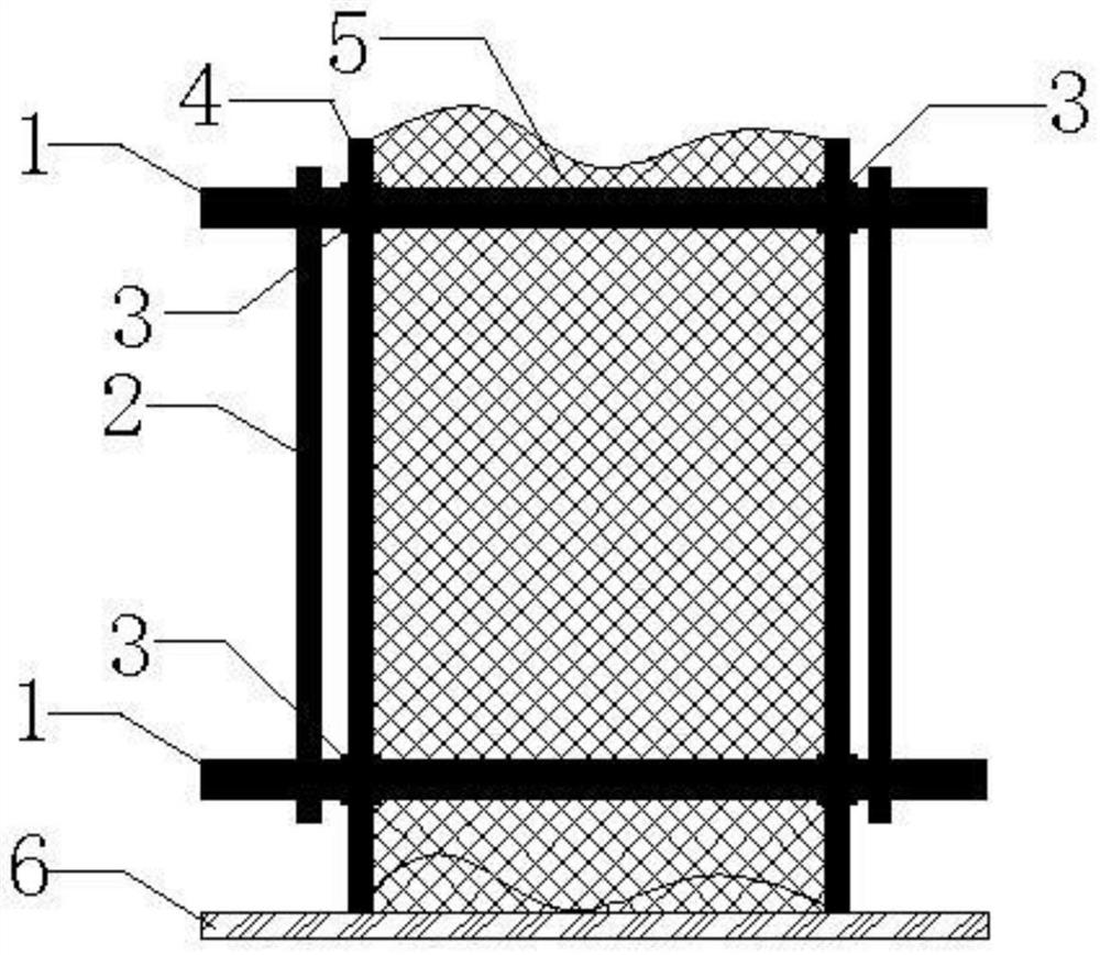
[0027] As shown in the accompanying drawings, a blocking method of cast-in-situ concrete at the joints of beams and columns is constructed by using a steel bar buckle tool 3 , a connecting rod 4 and a steel wire mesh 5 .

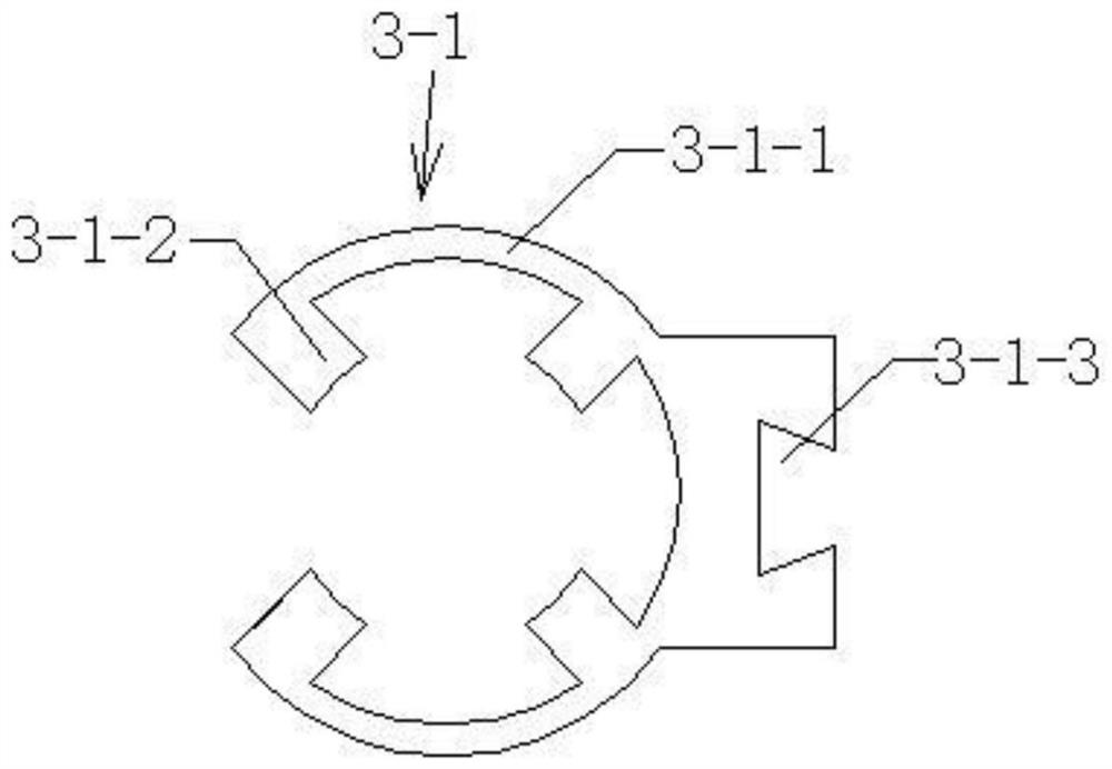
[0028] The steel buckle tool 3 includes a buckle A3-1 and a buckle B3-2, the buckle A3-1 includes a C-shaped ring-shaped buckle main body 3-1-1, and the buckle A3-1 The inner wall of the ring buckle main body 3-1-1 is provided with a plurality of inner teeth 3-1-2 integrated with it along its circumference, the inner teeth 3-1-2 are trapezoidal in design, and the inner teeth 3-1-2 The ends (one side of the trapezoidal short side) are all inclined to one side to form inverted teeth, so that when in use, the buckle can only slide to one side. A pin groove 3-1-3 is provided on the outer wall of the ring-shaped buckle main body 3-1...


PUM


Abstract

The invention discloses a blocking method for cast-in-place concrete at a beam-column joint part. Construction is conducted through a steel bar buckling tool, a connecting rod and a steel wire mesh, the steel bar buckling tool comprises a buckle A and a buckle B which can be connected together through a pin joint, a plurality of inner teeth are arranged on the inner walls of annular buckle bodies of the buckle A and the buckle B in the circumferential direction, and the ends of the inner teeth incline towards one side to form inverted teeth; the connecting rod can be buckled and connected with a buckle A or a buckle B of the steel bar buckling tool; a steel wire mesh with a fixed connecting rod is arranged in each concrete pouring unit formed by the adjacent longitudinal steel bars in the steel bar framework at the concrete blocking position, the steel wire meshes are arranged in the circumferential direction of the concrete pouring units and are in a U shape in the concrete pouring units, and the opening side of the U shape is in the concrete pouring direction. The connecting rods fixed to the steel wire meshes are connected with the steel reinforcement framework through steel reinforcement buckle tools, and a double-layer steel wire mesh is formed between every two adjacent concrete pouring units.

Description

technical field [0001] The invention relates to a blocking method of cast-in-place concrete for beam-column joints, which belongs to the technical field of building construction. Background technique [0002] The joints of beams and columns are poured with concrete of different strength grades. At present, when pouring concrete of different strength grades, the following two methods of pouring-in-place concrete are usually used: 1. Vertically to the direction of concrete pouring, bind on the bound steel skeleton 2. Vertically to the concrete pouring direction, insert wooden squares into the bound steel skeleton to form a block. Both of the above two cast-in-place concrete blocking methods have certain technical and quality problems: the first blocking method is inconvenient in construction (when the steel wire mesh is bound in the steel skeleton, for the binding point located at the bottom part of the steel skeleton, the construction personnel It is often impossible to bind...

Claims


Application Information

Patent Timeline
IPC IPC(8): E04G21/02E04G21/12E04C5/04E04C5/03
CPCE04G21/02E04G21/123E04C5/04E04C5/03
Inventor 白正茂陈思成马祖进李景泉田园园崔文胜胡涛
Owner SHANDONG SANJIAN CONSTR ENG MANAGEMENT
Learn More