Method for calculating safe drilling density of fractured formation

A drilling fluid density and formation technology, which is applied in the field of calculating safe drilling density in fractured formations, can solve problems such as the inability to consider the effects of formation wellbore stability and drilling fluid density, and incomplete drilling fluid density calculation.

Active Publication Date: 2022-05-31
SOUTHWEST PETROLEUM UNIV
View PDF13 Cites 0 Cited by
  • Summary
  • Abstract
  • Description
  • Claims
  • Application Information

AI Technical Summary

Problems solved by technology

[0007] When drilling into formations such as fractured zones, faults, and fractures, due to differences in basic assumptions and theories, it is impossible to consider the effects of factors such as the geometric occurrence of the formation on the stability of the wellbore wall and the density of the drilling fluid
Therefore, the above method is not fully applicable to the calculation of drilling fluid density in the drilling engineering of fractured zone, fault and fractured formation

Method used


Image

  • Method for calculating safe drilling density of fractured formation
  • Method for calculating safe drilling density of fractured formation
  • Method for calculating safe drilling density of fractured formation

Examples


Embodiment 1

rad;

By formula and, obtain the fracture curve function of the trigonometric function curve form on wellbore, as shown in formula:

[0071]

In the formula, A, B, C are plane control parameters; z is height, and its unit is m; r is wellbore radius, and its unit is m; θ is

Well circumference angle, its unit is rad;

Known high point coordinates H (x0, y0) and low point coordinates L (x1, y1), then formula is rewritten as following formula:

[0074]

In formula, θ is well circumference angle, and its unit is rad; z is height, and its unit is m; x

0

, y

0

is the high point coordinate, x

1

, y

1

low

coordinate;

Therefore inclination angle, azimuth, inclination and curve length in fracture parameters are respectively shown as following formula:

[0077]

β=min(x

0

,x

1

) (6)

[0079]

[0080]

In formula, α is inclination angle, and its unit is rad; β is trend, and its unit is rad; λ is tendency, and its unit is rad; 1 is

The length of the curve in...

Embodiment 2

[0108]

[0110] Table 1

[0111]

[0115]

[0125]

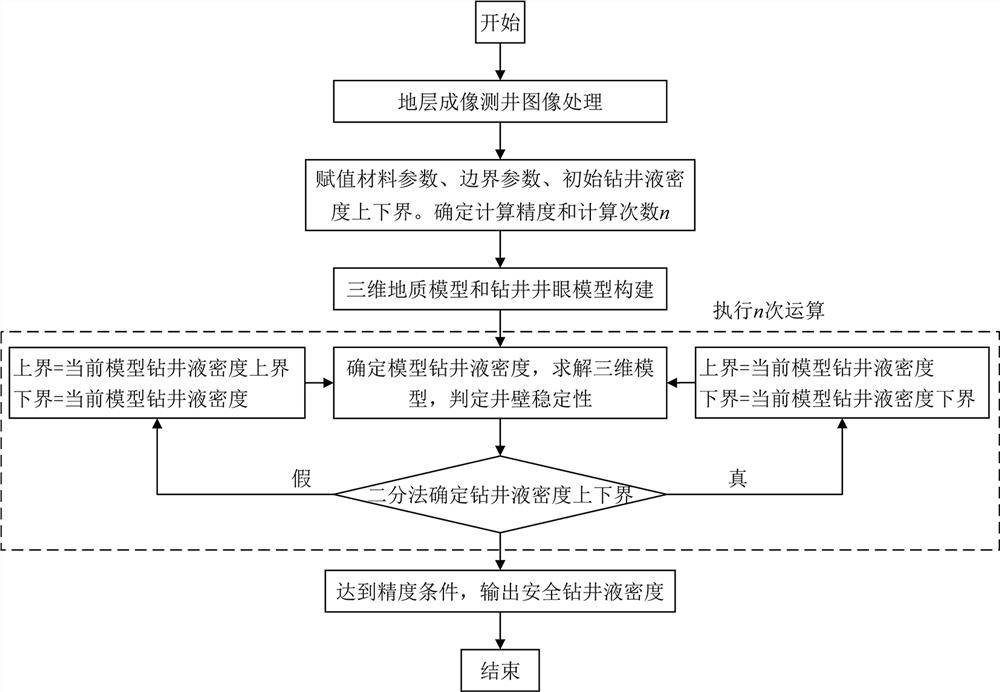
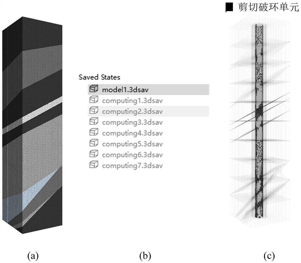
[0126] S4, utilize the discrete element method to solve the three-dimensional geological model to determine the stability of the wellbore.

[0129]

[0132]

[0133]

[0134] S6, repeat steps S4 to S5; the precision we set is 0.01, and the upper and lower limits of the drilling fluid density are 2.09 g /

[0136]

[0140] Since the formation does not have a fractured formation, the first step operation may be defaulted.

[0143]

[0153]

[0154] S4, using the discrete element method, solve the three-dimensional geological model, and determine the stability of the wellbore.

[0157]

[0160]

[0161]

[0162] S6, repeat steps S4 to S5; the precision we set is 0.01, and the upper and lower limits of the drilling fluid density are 2.09 g /

[0164]


PUM


Abstract

The invention discloses a method for calculating the safe drilling density of a fractured formation, and the method comprises the following steps: S1, processing an image, and recognizing an underground fracture; s2, a three-dimensional geologic model is established through underground fracture parameters, and a well drilling well model is established according to the size and length of a well; s3, assigning model material parameters, boundary conditions and upper and lower bounds of initial drilling fluid density, and then calculating precision; s4, solving the three-dimensional geologic model by using 3DEC discrete element software, and judging the stability of the well wall; s5, determining the upper and lower bounds of the drilling fluid density by using a bisection method; s6, repeatedly executing the steps S4-S5; and S7, after a set precision condition is reached, storing and outputting the safe drilling fluid density. According to the method, on the basis of the imaging logging diagram, the three-dimensional well model is established, the discrete element theory is used, the safe drilling fluid density is calculated, calculation of the drilling fluid density in a fracture zone, a fault and a fractured stratum can be more accurate, and drilling engineering drilling of the fractured stratum can be better guided.

Description

A method for calculating safe drilling density in fractured formations technical field The present invention relates to drilling practice in petroleum and natural gas engineering, geothermal drilling, the field of deep scientific exploration, especially The invention relates to a method for calculating safe drilling density in fractured strata. Background technique [0002] With the development of oil and gas engineering, the drilling depth is getting deeper and deeper. The formation encountered by drilling is often not complete. It is a solid rock, but a rock mass containing structural planes. This phenomenon is particularly prominent when drilling into broken zones, faults and fractures. Drilling a wellbore requires the support of drilling fluid pressure, otherwise problems such as borehole necking and collapse will occur. resulting in stuck drills, buried Drill pipe and other problems, in severe cases, the entire wellbore will be scrapped. Therefore, the requir...

Claims


Application Information

Patent Timeline
Patent Type & Authority Applications(China)
IPC IPC(8): G06F30/13E21B49/00G06F30/20G06T17/10G06F119/02
CPCG06F30/13G06F30/20G06T17/10E21B49/00G06F2119/02
Inventor 石祥超高雷雨刘建锋于浩代宇婷陈修平李清鲮李双贵王宇鸣
Owner SOUTHWEST PETROLEUM UNIV
Why Eureka
Try Eureka