Supercharge Your Innovation With Domain-Expert AI Agents!

Clinical hemodialysis conversion device for nephrology department

A hemodialysis and conversion device technology, applied in dialysis systems, suction equipment, etc., can solve the problems of entanglement, instability, and inconvenience of infusion tubes, and achieve the effects of preventing entanglement, reducing contact friction, and facilitating height adjustment

Pending Publication Date: 2022-06-03
驻马店市中心医院
View PDF0 Cites 0 Cited by
  • Summary
  • Abstract
  • Description
  • Claims
  • Application Information

AI Technical Summary

Problems solved by technology

[0003] When the existing dialysis conversion device is in use, the infusion tube on the hemodialysis conversion device is prone to entanglement, which makes it very inconvenient for medical staff to use it to treat patients. In order to facilitate mobile use, it is usually placed at the bottom of the dialysis conversion device Install rollers, these rollers will drive the device to move when the device is in use, it is very unstable

Method used


Image

  • Clinical hemodialysis conversion device for nephrology department
  • Clinical hemodialysis conversion device for nephrology department
  • Clinical hemodialysis conversion device for nephrology department

Examples


Embodiment 1

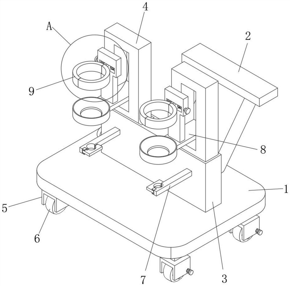
[0034] refer to Figure 1-6 The shown hemodialysis conversion device for clinical use in nephrology includes a mounting plate 1, the upper surface of the mounting plate 1 is provided with a stabilizing sleeve 3, the inner wall of the stabilizing sleeve 3 is slidably connected with a motion plate 4, and the inner wall of the motion plate 4 is slidably connected. A support plate 8 is provided, the upper surface of the mounting plate 1 is provided with a fixed rod, the top of the fixed rod is provided with a push plate 2, the lower surface of the mounting plate 1 is provided with a protective plate 5, and the inner wall of the protective plate 5 is rotatably connected with a roller 6, The front surface of the stabilization sleeve 3 is provided with a connecting rod 7 , and the upper surface of the support plate 8 is provided with a positioning stabilization mechanism 9 .

[0035] With the above structure, by setting the stabilizing sleeve 3, the movement of the moving plate 4 is ...

Embodiment 2

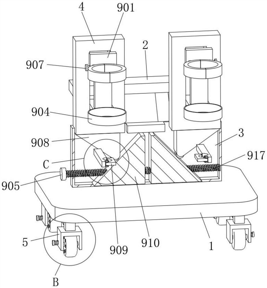
[0037] Based on the above-mentioned Embodiment 1, the positioning stabilization mechanism 9 includes a vertical vertical plate 901 disposed on the upper surface of the support plate 8 , the front surface of the vertical vertical plate 901 is provided with an escape groove 911 , and the opposite sides of the left and right vertical vertical plates 901 are provided with rotating The inner wall of the rotating hole is rotatably connected with a first positive and negative screw rod 912 . By setting the rotation hole, the first front and back screw rods 912 are avoided, and by setting the vertical vertical plate 901 , the stability of the first front and back screw rods 912 is maintained.

Embodiment 3

[0039] Based on the above-mentioned Embodiment 1 or 2, one end of the first front and back screw rod 912 is provided with a second knob 907, and the surfaces of the first front and back screw rod 912 are respectively screwed with the left clamp plate 903, the right clamp plate 902, the left clamp plate 903, the right clamp The back surface of the clamping plate 902 is slidably connected with the inner wall of the escape groove 911 , and the front surface of the support plate 8 is provided with an annular ring plate 904 . By setting the second knob 907, the operator rotates the second knob 907 to drive the first positive and negative screw rods 912 to rotate. By setting the left splint 903 and the right splint 902, the first positive and negative screw rods 912 rotate to drive the left splint 903 and the right splint 902. Close to each other, by arranging the annular ring plate 904, the objects placed in the annular ring plate 904 are supported.


PUM


Abstract

The invention discloses a clinical hemodialysis conversion device for the nephrology department, and relates to the field of medical devices.The clinical hemodialysis conversion device comprises a mounting plate, a stable sleeve is arranged on the upper surface of the mounting plate, a moving plate is slidably connected to the inner wall of the stable sleeve, a supporting plate is arranged on the inner wall of the moving plate, and a fixing rod is arranged on the upper surface of the mounting plate; and a push plate is arranged at the top end of the fixed rod. By arranging a stabilizing sleeve, stable movement of a moving plate is kept, by arranging a push plate, the push plate is conveniently pushed to drive the whole mounting plate to move, by arranging rollers, the whole mounting plate is conveniently moved, by arranging a supporting plate, the structure of a positioning stabilizing mechanism is supported, and by arranging the positioning stabilizing mechanism, the stability of the mounting plate is improved. By means of the structure, the height of the installation plate is adjusted, the infusion tube is prevented from being wound, meanwhile, the idler wheel is limited, and unstable rotation of the idler wheel is prevented.

Description

technical field [0001] The invention relates to the field of medical devices, in particular to a hemodialysis conversion device for clinical use in nephrology. Background technique [0002] Hemodialysis is one of the ways of renal replacement therapy for patients with acute and chronic renal failure. It drains the blood from the body to the outside of the body, and passes through a dialyzer composed of numerous hollow fibers. Substance exchange, removing metabolic wastes in the body, maintaining electrolyte and acid-base balance; at the same time removing excess water in the body, and returning the purified blood to the whole process is called hemodialysis. [0003] When the existing dialysis conversion device is in use, the infusion tube on the hemodialysis conversion device is prone to entanglement, which makes it very inconvenient for medical staff to use it to treat patients. Install rollers, these rollers will drive the device to move when the device is in use, which ...

Claims


Application Information

Patent Timeline
Patent Type & Authority Applications(China)
IPC IPC(8): A61M1/18
CPCA61M1/16
Inventor 陈强
Owner 驻马店市中心医院
Features
  • R&D
  • Intellectual Property
  • Life Sciences
  • Materials
  • Tech Scout
  • Unparalleled Data Quality
  • Higher Quality Content
  • 60% Fewer Hallucinations
Learn More