Automatic lead plate manufacturing device

A technology for manufacturing devices and lead plates, which is applied in the direction of manufacturing tools, casting molding equipment, casting mold components, etc., can solve the problems of long time consumption, low production efficiency, and easy fatigue of employees, and achieve the effect of avoiding bending

Inactive Publication Date: 2022-06-03
YANTAI ENG & TECH COLLEGE YANTAI TECHNICIAN INST
View PDF0 Cites 0 Cited by
  • Summary
  • Abstract
  • Description
  • Claims
  • Application Information

AI Technical Summary

Problems solved by technology

[0003] The procedure of manual production of lead plates is relatively cumbersome, the production efficiency is relatively low, and it takes a long time to meet the needs of mass production. Moreover, after a long period of repeated operations, employees are prone to fatigue and lack of concentration, which affects production efficiency.

Method used


Image

  • Automatic lead plate manufacturing device
  • Automatic lead plate manufacturing device
  • Automatic lead plate manufacturing device

Examples


Embodiment 1

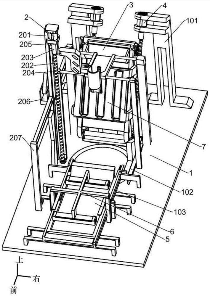
[0028] An automatic production device for lead plates, such as Figure 1-9 As shown, it includes a bottom plate 1, a first support frame 101, a first fixed frame 102, a second support frame 103, a first support column 104, a guide column 105, a forming plate 301, a reclaiming mechanism, a feeding mechanism and a material frame flipping Mechanism, a lead pool is arranged in the middle of the bottom plate 1, the lead pool is used to store the lead liquid, and two first support frames 101 are fixed symmetrically at the rear end of the top wall of the bottom plate 1. A second support frame 103 is fixed at the front end of the wall, a slideway is arranged on the second support frame 103, a first fixing frame 102 is fixed on the right side of the middle of the top wall of the bottom plate 1, the first fixing frame 102 is T-shaped, and the bottom plate 1 Two first support columns 104 are fixed symmetrically on the front side of the wall, the first support columns 104 are located on b...

Embodiment 2

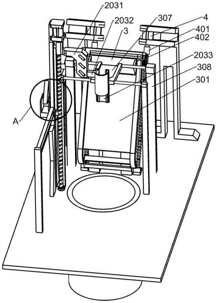
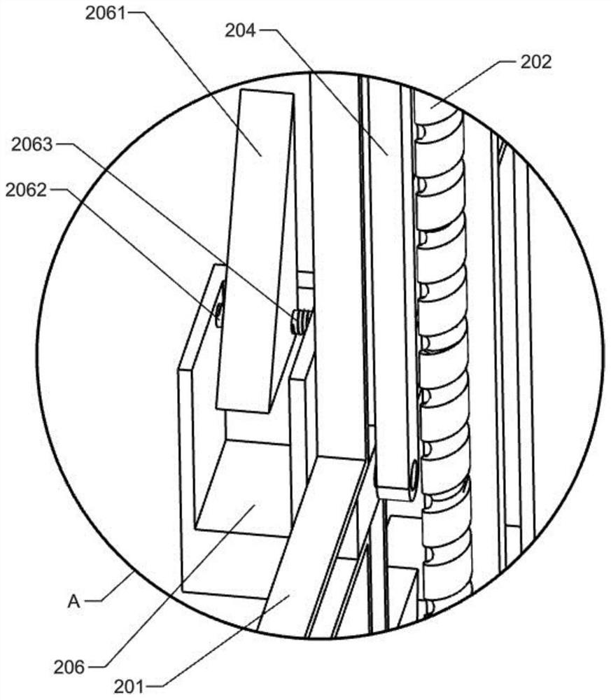
[0031] On the basis of Example 1, as Figure 1-4 As shown, the reclaiming mechanism includes a No. 1 motor 2, a third support frame 201, a first screw rod 202, a first bushing 203, a first connecting frame 2031, a reclaiming bucket 2032, a first sliding plate 2033, a first spring 2034, the first sliding block 205 and the second support column 207, a third support frame 201 is fixed on the left side of the top wall of the bottom plate 1, and two second support columns 207 are fixed symmetrically in front and rear on the left side of the top wall of the bottom plate 1. The second support column 207 is used to fix the third support frame 201, the front and rear ends of the third support frame 201 are fixed on the two second support columns 207, the third support frame 201 is cross-shaped, and the third support frame 201 is provided with two The slideway, the two slideways on the third support frame 201 are perpendicular to each other, the third support frame 201 is slidably conne...

Embodiment 3

[0038] On the basis of Example 2, as Figure 6-7 As shown, it also includes a No. 2 motor 4, a second bushing 401, a second screw 402, a third bushing 403, a push column 4031, a third spring 404, a first sliding rod 405, a second sliding block 406 and For the scraper 407 , a No. 2 motor 4 is installed on the top of each first support frame 101 , the No. 2 motor 4 is slightly inclined forward, and the output shaft of the No. 2 motor 4 is connected to the second screw rod through the second bushing 401 On 402, the No. 2 motor 4 drives the second screw rod 402 to rotate through the second bushing 401, the bottoms of the two second screw rods 402 are connected to the bottom plate 1 in rotation, and the two second screw rods 402 are inclined forward, each Each of the second screw rods 402 is covered with a third bushing 403, the third bushing 403 moves up and down as the second screw rod 402 rotates, and a pusher 403 is fixed on the right wall of the third bushing 403 on the right ...


PUM


Abstract

The invention discloses an automatic lead plate manufacturing device which comprises a bottom plate, a first supporting frame, a first fixing frame, a second supporting frame, a first supporting column, a guide column, a forming plate and the like. A lead pool is arranged in the middle of the bottom plate, two first supporting frames are fixed to the rear end of the top wall of the bottom plate in a bilateral symmetry mode, a second supporting frame is fixed to the front end of the top wall of the bottom plate, a first fixing frame is fixed to the right side of the middle of the top wall of the bottom plate, and two first supporting columns are fixed to the front side of the top wall of the bottom plate in a bilateral symmetry mode. Two guide columns are bilaterally symmetrically fixed to the front side of the top wall of the bottom plate, and a forming plate is fixed to the rear side of the top wall of the bottom plate. The functions of lead liquid taking, lead liquid conveying and lead liquid pouring can be achieved through mutual cooperation of the material taking mechanism, the feeding mechanism and the material frame overturning mechanism only by starting the first motor, extra manpower does not need to be consumed, and the lead liquid taking and conveying device can run all the time under the non-stop condition.

Description

technical field [0001] The invention relates to an automatic device, in particular to an automatic production device of a lead plate. Background technique [0002] Most of the current lead plate manufacturers still use traditional manual production methods when making lead plates. When making lead plates, workers first take out the lead solution in the lead pool with a tool for scooping lead solution, and then pour the lead solution into the lead solution temporarily. After that, the lead liquid in the temporary storage box is manually poured into the forming plate, and the lead liquid will flow down along the forming plate, and the excess lead liquid will fall directly into the lead pool. After the lead plate is formed, The lead plate is then removed by another worker. [0003] The procedure of manual production of lead plates is cumbersome, the production efficiency is relatively low, and it takes a long time to meet the needs of mass production. Moreover, after a long pe...

Claims


Application Information

Patent Timeline
Patent Type & Authority Applications(China)
IPC IPC(8): B22C9/06B22C9/22B22D35/04B22D29/04
CPCB22C9/06B22C9/22B22D35/04B22D29/04Y02E60/10
Inventor 段玮玮张伟孙慧孙红梅马海洋
Owner YANTAI ENG & TECH COLLEGE YANTAI TECHNICIAN INST
Why Eureka
Try Eureka