Valve element material increasing and decreasing method and valve element structure

A technology of adding and subtracting materials and valve cores, which is applied in the direction of additive processing, valve devices, mechanical equipment, etc., can solve the problems of low forming efficiency, difficult to guarantee the accuracy of flow channel size and inner surface, easy deformation, etc., and achieve the goal of flow channel structure Stability, saving printing time, ideal forming accuracy

Pending Publication Date: 2022-06-03
广东增减材科技有限公司
View PDF0 Cites 2 Cited by
  • Summary
  • Abstract
  • Description
  • Claims
  • Application Information

AI Technical Summary

Problems solved by technology
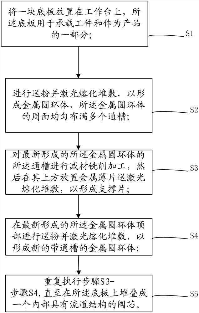
Some traditional factories use brazing process to stack multi-layer metal sheets to manufacture the valve core, but the valve core has low structural strength and is not suitable for long-term use in a high-pressure environment. If it is used for a long time, it will Cause the valve core to collapse or crack as a whole
Other factories try to use SLM laser powder bed for powder laying additive manufacturing, but the flow channel structure 200 of the valve core manufactured by the existing additive process is easy to deform, the size of the flow channel and the accuracy of the inner surface are difficult to guarantee, and the forming efficiency is low

Method used


Image

  • Valve element material increasing and decreasing method and valve element structure
  • Valve element material increasing and decreasing method and valve element structure
  • Valve element material increasing and decreasing method and valve element structure

Examples


Embodiment Construction

[0026] The technical solutions in the embodiments of the present application will be clearly and completely described below with reference to the drawings in the embodiments of the present application. Obviously, the described embodiments are only a part of the embodiments of the present application, rather than all the embodiments. The components of the embodiments of the present application generally described and illustrated in the drawings herein may be arranged and designed in a variety of different configurations. Thus, the following detailed description of the embodiments of the application provided in the accompanying drawings is not intended to limit the scope of the application as claimed, but is merely representative of selected embodiments of the application. Based on the embodiments of the present application, all other embodiments obtained by those skilled in the art without creative work fall within the protection scope of the present application.

[0027] It sh...


PUM

PropertyMeasurementUnit
particle sizeaaaaaaaaaa
thicknessaaaaaaaaaa

Abstract

The invention relates to the technical field of additive and subtractive forming, and provides a valve element additive and subtractive method and a valve element structure.The valve element additive and subtractive method comprises the following steps that S1, a bottom plate is placed on a workbench, and the bottom plate is used for bearing a workpiece and serves as a part of a product; s2, powder feeding and laser melting stacking are carried out, so that a metal circular ring body is formed, and a plurality of through grooves are evenly distributed in the circumferential face of the metal circular ring body; s3, carrying out subtractive milling on the newly formed through groove of the metal circular ring body, and then placing a metal sheet above the newly formed through groove to form a supporting sheet; s4, powder feeding and laser melting stacking are conducted on the top of the newly-formed metal circular ring body, so that a new metal circular ring body with a through groove is formed; s5, the step S3 to the step S4 are executed repeatedly till a valve element with a flow channel structure inside is stacked on the bottom plate; the method has the beneficial effects that the runner forming precision is high, and time and materials are saved.

Description

technical field [0001] The present application relates to the technical field of material addition and subtraction forming, and in particular, to a valve core material addition and reduction method and a valve core structure. Background technique [0002] Traditional processing industries generally cannot directly and integrally manufacture part structures with complex internal flow channels through machining methods. The laser melting deposition forming technology is based on the principle of additive manufacturing, which is especially suitable for the integrated manufacturing of components with complex internal structures. This technology is more and more used in the processing and manufacturing of molds and water-cooled plate parts with internal cavities, but this technology also needs to abide by certain rules during the processing and manufacturing of parts with internal cavities. products with the ideal structure. [0003] There is a commonly used industrial regulati...

Claims


Application Information

Patent Timeline
Patent Type & Authority Applications(China)
IPC IPC(8): B22F10/25B22F10/50B33Y10/00B33Y80/00B23P15/00F16K51/00
CPCB22F10/25B22F10/50B33Y10/00B33Y80/00B23P15/001F16K51/00Y02P10/25
Inventor 卓炎廖文勇
Owner 广东增减材科技有限公司
Why Eureka
Try Eureka