Construction method for anti-floating beam of subway station

A construction method and technology for subway stations, applied in artificial islands, water conservancy projects, infrastructure projects, etc., can solve the problems of difficult construction and poor anti-floating effect, and achieve the effects of convenient pouring construction, dense connection and stable support structure

Pending Publication Date: 2022-06-03
CHINA RAILWAY 12TH BUREAU GRP +1
View PDF6 Cites 0 Cited by
  • Summary
  • Abstract
  • Description
  • Claims
  • Application Information

AI Technical Summary

Problems solved by technology

Due to the construction of the anti-floating beam in the gap between the crown beam and the roof of the station, the space is characterized by airtightness, which makes its construction difficult
The common construction method of anti-floating beams is to fix the simple formwork on the roof of the station, and leave pouring holes for pouring. This method cannot make the concrete fully dense, resulting in poor anti-floating effect

Method used


Image

  • Construction method for anti-floating beam of subway station
  • Construction method for anti-floating beam of subway station
  • Construction method for anti-floating beam of subway station

Examples


Embodiment Construction

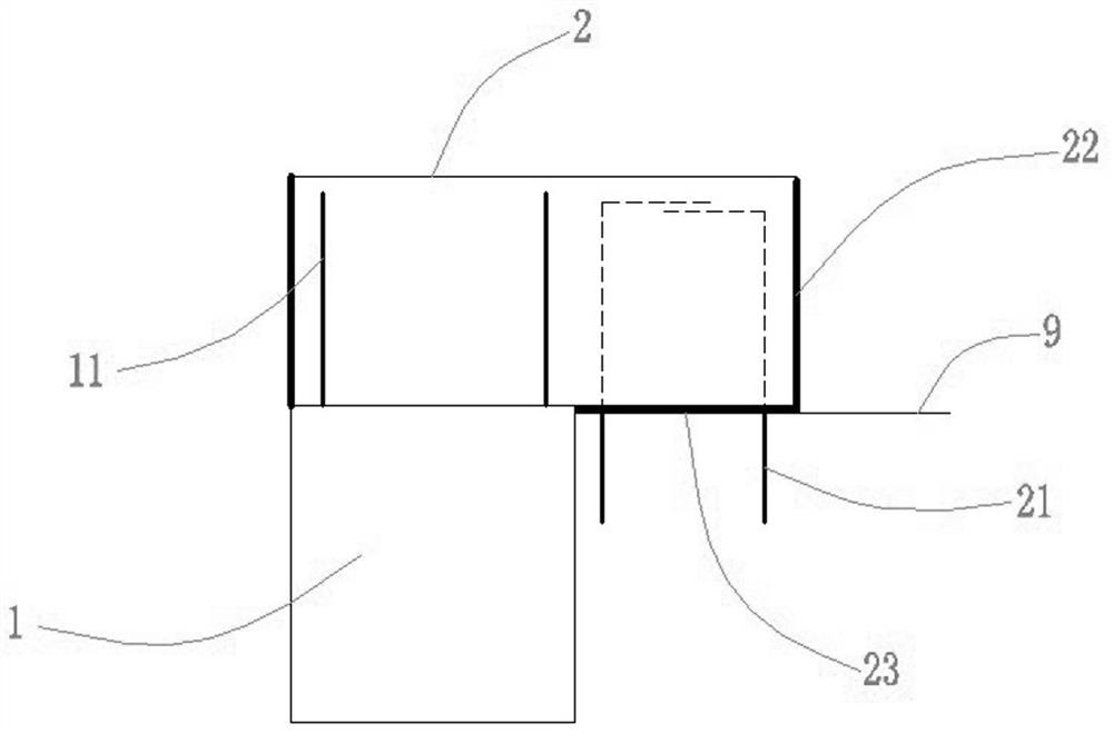
[0016] refer to Figure 1 to Figure 6 The present invention is further elaborated, and a construction method for anti-floating beams in a subway station comprises the following steps:

Step 1, the top of the underground diaphragm wall 1 is applied as a crown beam 2, and two crown beam reserved steel bars 21 are arranged at the contact position of the crown beam 2 and the anti-floating beam 4, which are used for the connection between the crown beam 2 and the anti-floating beam 4. ;

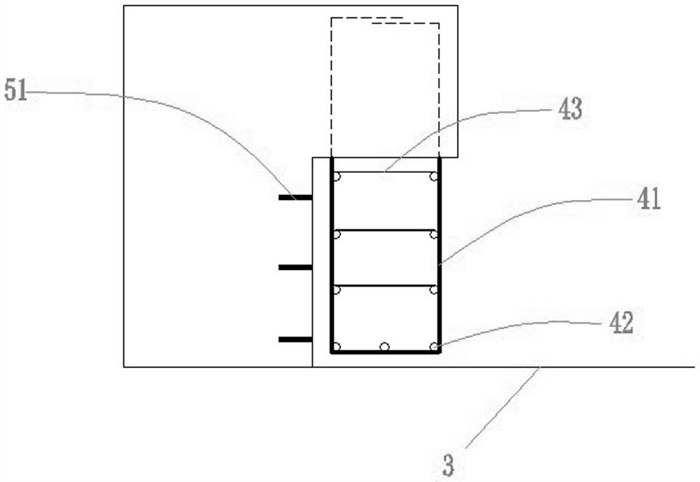
Step 2, install anti-floating beam reinforcing bars, the anti-floating beam reinforcing bars include anti-floating beam main bars 41, anti-floating beam distribution bars 42 and anti-floating beam tension bars 43, connect the anti-floating beam main bars 41 with the reserved steel bars 21 of the crown beam, and at the same time Three expansion bolts 51 are arranged in sequence from top to bottom on the wall surface of the underground continuous wall 1 facing the floating beam 4;
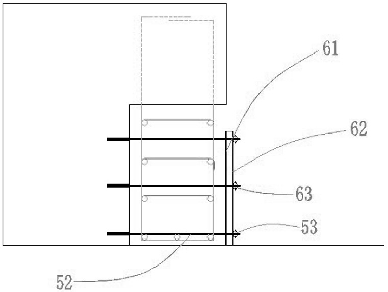
Step 3: Install ...


PUM


Abstract

The invention belongs to the field of metro station structure construction, and particularly relates to a metro station anti-floating beam construction method which is used for pouring an anti-floating beam in a space below a top beam on a station top plate and preventing a station main body structure from integrally floating due to the influence of water floating, and comprises the following steps: pre-burying two reinforcing steel bars and installing anti-floating beam reinforcing steel bars when the top beam is constructed; the method comprises the following steps: embedding three expansion bolts into a ground wall surface, mounting an anti-floating beam straight wall section formwork system, fixing a formwork by adopting an inner tie bar, erecting a vertical formwork system, mounting and fixing an over-irrigation area formwork, fixing an outer formwork system by adopting an inclined steel pipe and a steel bar, pouring anti-floating beam concrete in a layered manner, shoveling the over-irrigation area concrete, and dismounting the formwork system. The formwork structure is firm, the supporting structure is stable, and concrete pouring construction is facilitated. The method is reasonable in design and convenient to operate, the roof waterproof layer structure is not damaged, the anti-floating beam and the top beam bottom are tightly connected, and the effect is remarkable.

Description

technical field [0001] The invention belongs to the field of subway station structure construction, and particularly relates to a construction method for an anti-floating beam of a subway station. Background technique [0002] After the construction of the main structure of the subway station is completed, in order to prevent the station from being affected by water floating and the overall floating in the later stage, it is necessary to construct anti-floating beams to densely connect the main structure of the station and the crown beams in the enclosure structure. Because the anti-floating beam is constructed in the gap between the crown beam and the station roof, the space has the characteristics of airtightness, which makes its construction difficult. The common construction method of anti-floating beam is to simply fix the vertical form on the roof of the station, and leave pouring holes for pouring. This method cannot make the concrete fully compact, resulting in poor ...

Claims


Application Information

Patent Timeline
Patent Type & Authority Applications(China)
IPC IPC(8): E02D31/12E02D29/045
CPCE02D31/12E02D29/04
Inventor 任巍杰杜传球杨光辉吴广贺
Owner CHINA RAILWAY 12TH BUREAU GRP
Why Eureka
Try Eureka