
Floor protective door fixed through waste steel pipes

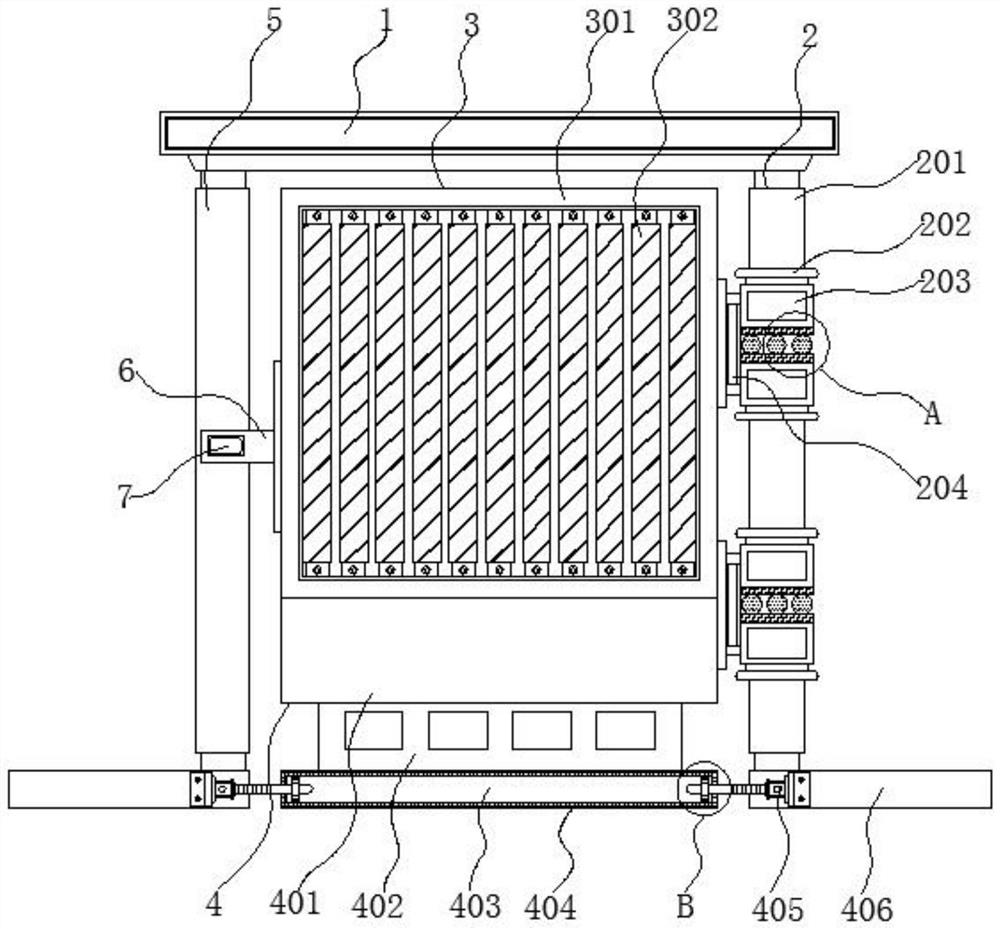
A technology for protecting doors and steel pipes, applied in the field of steel pipes, can solve the problems of inability to ensure smooth entry and exit of domestic pets, poor device positioning and braking performance, and easy to make loud noises, so as to ensure secondary utilization performance and achieve mutual positioning. performance, avoid the effect of thermal expansion and contraction

Inactive Publication Date: 2022-06-03
台州市锦成工程管理服务有限公司
View PDF0 Cites 0 Cited by
  • Summary
  • Abstract
  • Description
  • Claims
  • Application Information

AI Technical Summary

Problems solved by technology

[0004] The object of the present invention is to provide a kind of using waste steel pipes to fix the floor protective door, so as to solve the problem that the existing cutting equipment for computer chip processing proposed in the above background technology is easy to make a large sound during the process of turning and opening and closing. Fluency, at the same time, it is impossible to guarantee the smooth entry and exit of domestic pets, and it is often hindered by the protective door, and the positioning and braking performance of the whole device is not good, and the flexibility is insufficient.

Method used


Image

  • Floor protective door fixed through waste steel pipes
  • Floor protective door fixed through waste steel pipes
  • Floor protective door fixed through waste steel pipes

Examples


Embodiment Construction

[0026] The technical solutions in the embodiments of the present invention will be clearly and completely described below with reference to the accompanying drawings in the embodiments of the present invention. Obviously, the described embodiments are only a part of the embodiments of the present invention, but not all of the embodiments. Based on the embodiments of the present invention, all other embodiments obtained by those of ordinary skill in the art without creative efforts shall fall within the protection scope of the present invention.

[0027] In the description of the present invention, unless otherwise stated, "plurality" means two or more; the terms "upper", "lower", "left", "right", "inner", "outer" The orientation or positional relationship indicated by , "front end", "rear end", "head", "tail", etc. are based on the orientation or positional relationship shown in the accompanying drawings, and are only for the convenience of describing the present invention and ...


PUM


Abstract

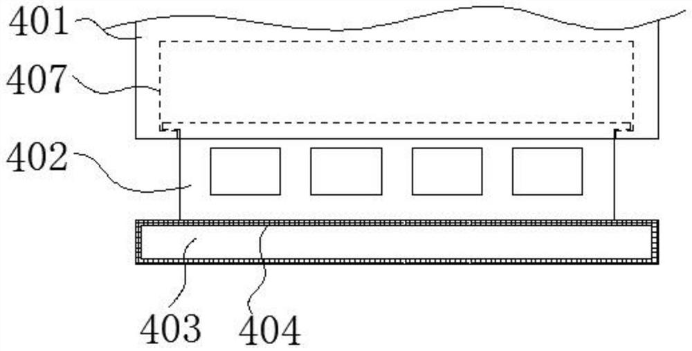
The invention discloses a floor protection door fixed through waste steel pipes, and relates to the technical field of computer chip machining, the floor protection door comprises a top plate and an adjusting assembly, an anti-jamming assembly is fixed to the right end of the bottom of the top plate, and a constant-temperature protection assembly is installed at the end, close to the vertical central axis of the top plate, of the anti-jamming assembly; and the adjusting assembly is fixed to the bottom of the constant-temperature protection assembly, a clamping ring is welded to the left end of the constant-temperature protection assembly, a clamping groove is clamped in the middle of the clamping ring, and a second supporting rod is welded to the outer wall of the rear end of the clamping groove. According to the floor protective door fixed through the waste steel pipes, the connecting plate fixed to the top of the baffle is movably pulled into the sliding groove formed in the fixing plate, through pulling, the gap space between the baffle and the ground can be adjusted, pets can go and go freely, convenience is provided for pet lovers, and the practicability is high. And the magnet strip adhered to the outer wall of the baffle can be adsorbed to the bottom of the fixing plate, so that the mutual positioning performance between the baffle and the fixing plate is realized.

Description

technical field [0001] The invention relates to the technical field of steel pipes, in particular to a floor protection door fixed by using waste steel pipes. Background technique [0002] Steel pipes have hollow sections that are much longer than the diameter or circumference of steel. According to the cross-sectional shape, it is divided into circular, square, rectangular and special-shaped steel pipes; according to the material, it is divided into carbon structural steel pipes, low-alloy structural steel pipes, alloy steel pipes and composite steel pipes; Steel pipes for thermal equipment, petrochemical industry, machinery manufacturing, geological drilling, high-pressure equipment, etc.; according to the production process, they are divided into seamless steel pipes and welded steel pipes, of which seamless steel pipes are divided into hot-rolled and cold-rolled. Welded steel pipes are divided into straight seam welded steel pipes and spiral seam welded steel pipes. Si...

Claims


Application Information

Patent Timeline
IPC IPC(8): E06B5/10E06B9/01E06B7/32E05B51/02E05D7/00E05D5/14E05D5/10
CPCE06B5/10E06B9/01E06B7/32E05B51/02E05D7/00E05D5/14E05D5/10
Inventor 林星友何敏
Owner 台州市锦成工程管理服务有限公司
Learn More