Siphon type liquid level control valve and control method thereof

A liquid level control, siphon type technology, applied in the field of liquid level control valves, can solve the problems of the main valve or float valve opening and closing, unstable opening and closing, pressure fluctuating high and low, internal valve difficult to close, etc. To achieve the effects of not being prone to a large amount of water overflow, preventing leakage and reducing flow

Active Publication Date: 2022-06-03
KAIWEIXI VALVE GRP CO LTD
View PDF7 Cites 0 Cited by
  • Summary
  • Abstract
  • Description
  • Claims
  • Application Information

AI Technical Summary

Problems solved by technology

Although the existing old-fashioned rod float valve has a good sealing effect, it often has some defects: for example, when the waves on the water surface are relatively large, it will cause the main valve or float valve to be in an unstable state of opening and closing. The valve is difficult to close in a short time
In this way, it is easy to cause the pressure to fluctuate, and even water hammer, resulting in easy damage to the valve and a large amount of water overflow.

Method used


Image

  • Siphon type liquid level control valve and control method thereof
  • Siphon type liquid level control valve and control method thereof
  • Siphon type liquid level control valve and control method thereof

Examples


Embodiment Construction

[0019] The present invention will be further described below in conjunction with the accompanying drawings:

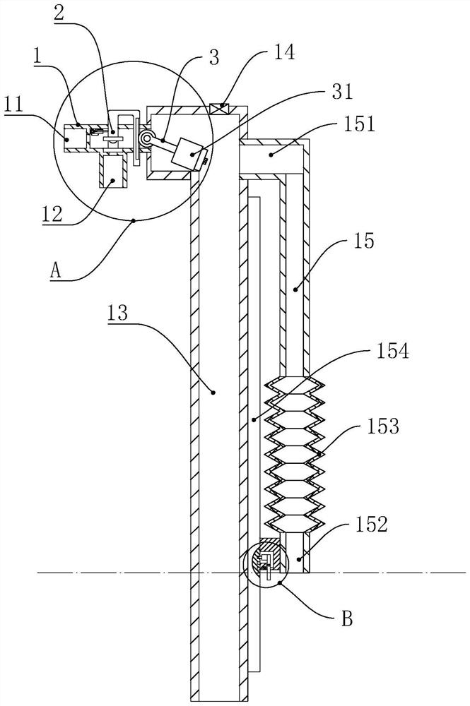
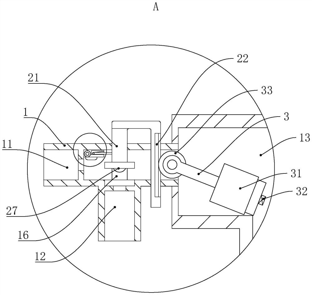
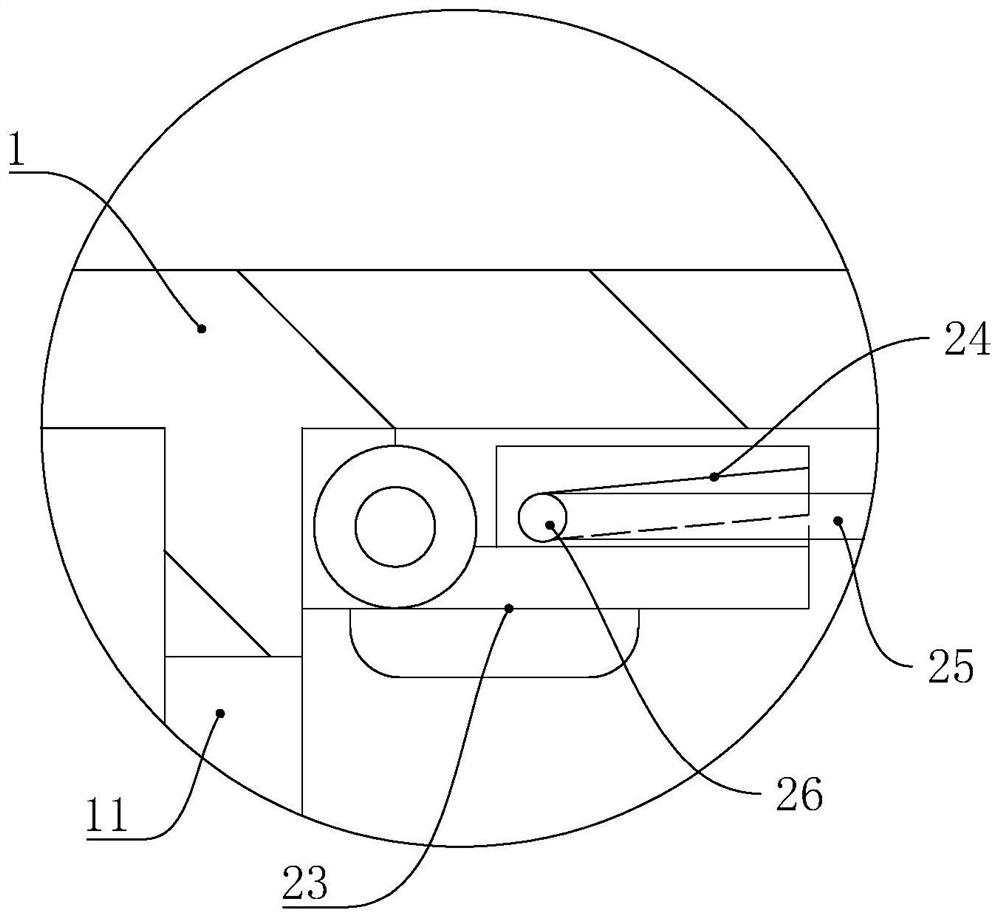
[0020] Referring to the drawings: the siphon type liquid level control valve in this embodiment includes a floating ball valve. The floating ball valve includes a valve body 1, a valve core 2, a crank arm 3 and a floating ball 31. The two ends of the crank arm 3 are respectively Connected with the valve core 2 and the floating ball 31, the valve body 1 is provided with a water inlet 11 and a water outlet 12 that communicate with each other. When the crank arm 3 rotates, the valve core 2 is driven to move, so that the valve The core 2 gradually closes the water inlet 11, which is characterized in that: the valve body 1 is fixedly connected with a cylinder body 13 with an open lower end, the crank arm 3 and the floating ball 31 are located in the cylinder body 13, and the upper end of the cylinder body 13 is located in the cylinder body 13. Closed and provided with a one...


PUM


Abstract

The siphon type liquid level control valve comprises a floating ball valve, the floating ball valve comprises a valve body, a valve element, a crank arm and a floating ball, the two ends of the crank arm are connected with the valve element and the floating ball respectively, a water inlet and a water outlet which are communicated with each other are formed in the valve body, and the crank arm drives the valve element to move when rotating. The valve body is fixedly connected with a cylinder with an opening in the lower end, the crank arm and the floating ball are located in the cylinder, the upper end of the cylinder is closed and provided with a one-way exhaust valve, the side portion of the cylinder is provided with a siphon, the upper end of the siphon is provided with a connecting pipe opening communicated with the upper end of the cylinder, and the connecting pipe opening is communicated with the lower end of the cylinder. A liquid inlet pipe orifice is formed in the lower end of the siphon, and the horizontal position of the liquid inlet pipe orifice is higher than that of the lower end opening of the barrel. The siphon principle is used for working, the water level height can be effectively controlled within a certain range, pressure fluctuation caused by frequent opening and closing of the valve is avoided, and the safety of a pipeline is improved.

Description

technical field [0001] The invention relates to the technical field of liquid level control valves, in particular to a siphon type liquid level control valve and a control method thereof. Background technique [0002] At present, the floating ball valve is a hydraulic water level control valve, which has the function of automatically opening and closing the valve pipeline to control the water level. It can be used as a pilot valve to control the opening and closing of the main valve on the water inlet pipe. Due to its good sealing performance, the floating ball valve It is widely used in various water tower (pool) automatic water supply systems in industrial and mining enterprises and civil buildings. It is easy to install and has high activation sensitivity. Although the existing old-fashioned rod float valve has a good sealing effect, it often has some defects: for example, when the waves on the water surface are relatively large, it will cause the main valve or the float ...

Claims


Application Information

Patent Timeline
Patent Type & Authority Applications(China)
IPC IPC(8): F16K31/24F16K31/34F16K31/54F16K27/02
CPCF16K31/24F16K31/34F16K31/54F16K27/02
Inventor 林文理胡锦旭陈群陈创造郑重林理杰丁晓月陈建设叶显斌
Owner KAIWEIXI VALVE GRP CO LTD
Why Eureka
Try Eureka