
Cooler

A cooler and cooling core technology, applied to indirect heat exchangers, heat exchanger types, heat exchanger shells, etc., can solve the problems of internal flow channel leakage, large footprint, and affecting the heat exchange efficiency of coolers, etc., to achieve The effect of reducing heat exchange speed and improving heat exchange efficiency

Active Publication Date: 2022-06-03
ZHEJIANG ERG TECH
View PDF11 Cites 2 Cited by
  • Summary
  • Abstract
  • Description
  • Claims
  • Application Information

AI Technical Summary

Problems solved by technology

The cooling pipeline of the traditional cooler is complicated to bend and occupies a large volume; the internal flow channel is prone to leakage, and part of the oil flows directly to the oil outlet without passing through the cooling pipeline, and there will be a gap between the cooling cavity and the outside through the shell. Heat exchange, which affects the heat exchange efficiency of the cooler

Method used


Image

  • Cooler
  • Cooler
  • Cooler

Examples


Embodiment 1

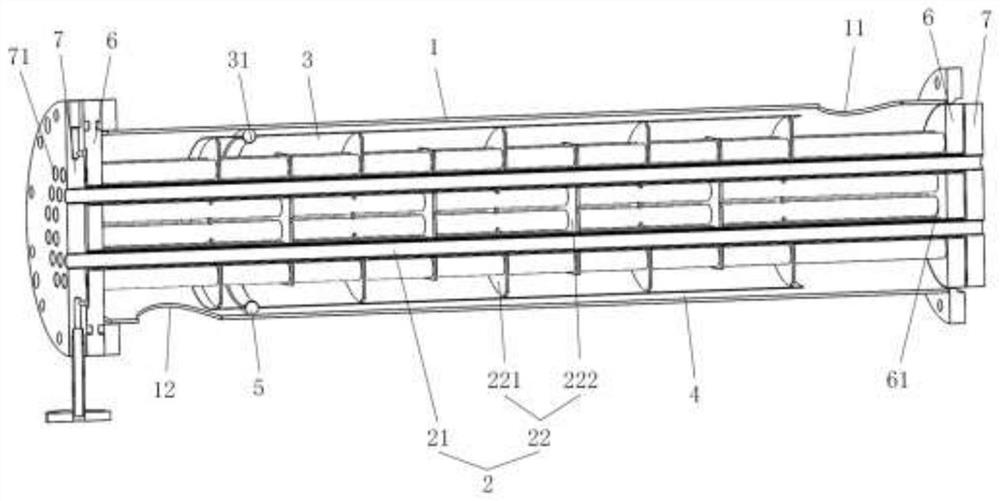
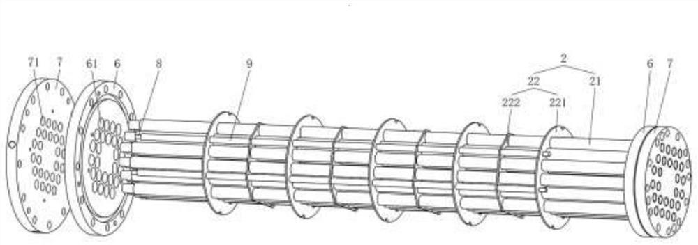
[0039] like figure 1 , figure 2 , a cooler, including a cylindrical shell 1, a cooling core group 2 and an inner tank 3 installed through the shell 1; the two ends of the shell 1 are respectively provided with an oil inlet 11 and an oil outlet 12; the cooling core group 2 It includes a flow pipe 21 and a guide plate 22 , and the flow pipe 21 and the guide plate 22 are installed inside the inner tank 3 ; an oil storage cavity 4 is formed between the outer wall of the inner tank 3 and the shell 1 .

[0040] Therefore, installing the inner tank 3 between the deflector 22 and the casing 1 can form a seal at the edge of the deflector 22 to ensure that the oil is cooled through the through-flow pipe 21 and improve the heat exchange efficiency; the oil storage cavity 4. The inner oil flows in, and an oil layer that does not participate in the cooling cycle is formed between the inner tank 3 and the shell 1, which can play a certain role of heat insulation, reduce the heat exchange ...

Embodiment 2

[0054] like figure 1 The outer wall of the inner tank 3 is provided with a sealing member installation groove 31 , and a sealing member 5 is installed in the sealing member installation groove 31 .

[0055] Therefore, the seal 5 generally adopts an O-ring to ensure that the oil will not leak from the seal.

[0056] like figure 1 , the seal installation groove 31 is located at one end of the outer wall of the inner tank 3 close to the oil outlet 12 .

[0057] In this way, the oil storage cavity 4 covers the entire cooling core group 2 to ensure the thermal insulation performance of the cooling core group 2 , thereby improving the heat exchange efficiency of the cooler.

[0058] like figure 1 , the thickness of the oil storage cavity 4 is 0.8mm-2mm.

[0059] Therefore, the insufficient thickness of the oil storage cavity 4 will affect the thermal insulation performance, and if the thickness is too large, the volume of the cooler will be increased. Controlling its thickness t...

Embodiment 3

[0061] like figure 1 , figure 2 , the cooler also includes an inner pipe cover plate 6, which is installed at both ends of the casing 1 and forms a seal with the casing 1; the inner pipe cover plate 6 is provided with an inner pipe installation hole 61, and the flow through Both ends of the tube 21 are inserted into the inner tube mounting holes 61 for installation.

[0062] Therefore, the inner pipeline cover plate 6 is used to seal both ends of the casing 1, and provides a cooling liquid interface for the through-flow pipe 21, which can make the structure of the cooler more compact and the installation more convenient.

[0063] like figure 1 , figure 2 , the cooler also includes an outer pipeline cover plate 7, the outer pipeline cover plate 7 is installed on the outside of the inner pipeline cover plate 6 and is flanged to the inner pipeline cover plate 6; the outer pipeline cover plate 7 is provided with The outer pipe installation hole 71 is inserted into the outer ...


PUM


Abstract

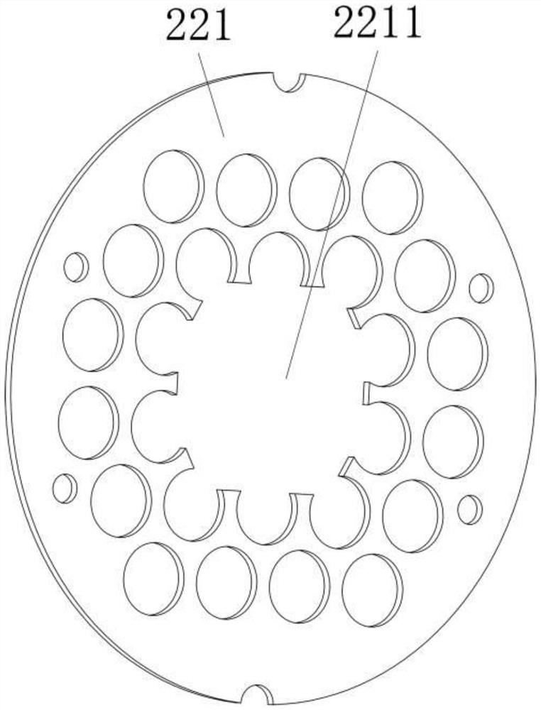
A cooler comprises a cylindrical shell, a cooling core set and an inner container, wherein the cooling core set and the inner container penetrate through the shell to be installed. An oil inlet and an oil outlet are respectively formed in two ends of the shell; the cooling core group comprises a through-flow pipe and a flow guide plate, and the through-flow pipe and the flow guide plate are mounted in the inner container; an oil storage cavity is formed between the outer wall of the inner container and the shell. The flow guide plate comprises an inner through plate and an outer through plate, plate bodies of the inner through plate and the outer through plate are provided with open holes for the through-flow pipe to penetrate through, and the through-flow pipe perpendicularly penetrates through the open holes of the inner through plate and the outer through plate and is sealed with the open holes. According to the cooler, the inner container is installed between the flow guide plate and the shell, sealing can be formed at the edge of the flow guide plate, it is guaranteed that oil liquid passes through the through-flow pipe to be cooled, and the heat exchange efficiency is improved; in addition, the oil storage cavity is formed between the inner container and the shell, oil flows into the oil storage cavity, an oil layer which does not participate in cooling circulation is formed between the inner container and the shell, a certain heat insulation effect can be achieved, the heat exchange speed of the inner space and the outer space of the shell is reduced, and the heat exchange efficiency of the cooler is further improved.

Description

technical field [0001] The invention relates to the field of new energy power generation cooling equipment, and more particularly to a cooler. Background technique [0002] With the development of science and technology, the power generation modes are becoming more and more diversified. From the original hydropower, thermal power, nuclear fuel power generation, etc., some new energy power generation (including onshore wind power generation, offshore wind power generation, photovoltaic power generation, etc.) has been added. etc.), like hydroelectric power generation and new energy power generation, in general, the available space for equipment is small. This requires the volume of power generation equipment and cooling equipment to be reduced as much as possible to ensure that equipment with sufficient power is installed in an effective space. The traditional cooling pipeline of the cooler is complicated to bend and occupies a large volume; the internal flow channel is pron...

Claims


Application Information

Patent Timeline
Patent Type & Authority Applications(China)
IPC IPC(8): F28D7/16F28F9/22F28F9/00
CPCF28D7/1676F28F9/22F28F9/005F28F2009/226Y02E10/72
Inventor 王电辉俞天翔王捷黎贤钛王汪洋朱灵灿石同中
Owner ZHEJIANG ERG TECH
Learn More