Scramjet tracing plif multi-parameter distribution measurement device and method

A scramjet and measuring device technology, applied in gas turbine engine testing, jet engine testing, image analysis, etc., can solve the problem that temperature and pressure settings cannot meet the scramjet test conditions, tracer PLIF spectrum and components The relationship between concentration, temperature and pressure is not clear, and there are no tracer PLIF measurements, etc.

Active Publication Date: 2022-07-29
NAT UNIV OF DEFENSE TECH
View PDF0 Cites 0 Cited by
  • Summary
  • Abstract
  • Description
  • Claims
  • Application Information

AI Technical Summary

Problems solved by technology

[0006] (1) The tracer PLIF signal is related to the component concentration, temperature and pressure, but the relationship between the tracer PLIF spectrum and the component concentration, temperature and pressure is not clear;
[0007] (2) The range of temperature and pressure in the test environment of the scram engine is relatively wide, and the post-calibration of the PLIF image is very important. At present, there is no tracer PLIF measurement and calibration method for this test environment
[0008] (3) The tracer PLIF post-calibration equipment is very important, but the existing calibration calibration equipment cannot meet the scramjet test conditions in terms of temperature and pressure settings

Method used


Image

  • Scramjet tracing plif multi-parameter distribution measurement device and method
  • Scramjet tracing plif multi-parameter distribution measurement device and method
  • Scramjet tracing plif multi-parameter distribution measurement device and method

Examples


Embodiment Construction

[0037] In order to make the objectives, technical solutions and advantages of the present invention clearer, the present invention will be further described in detail below with reference to the accompanying drawings and embodiments. It should be understood that the specific embodiments described herein are only used to explain the present invention, but not to limit the present invention.

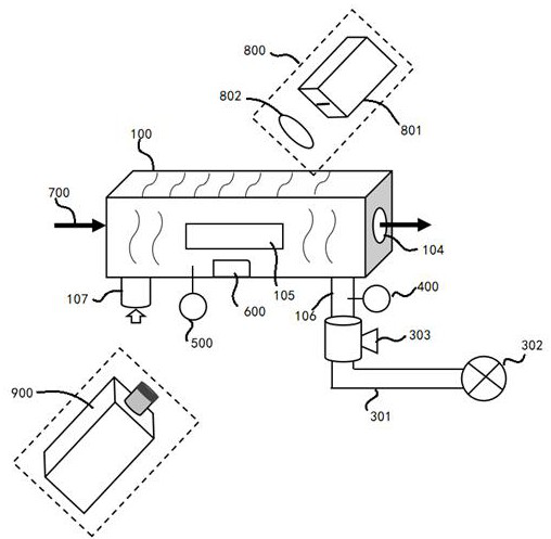
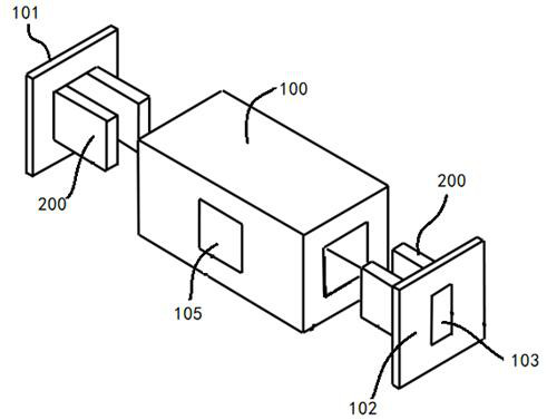
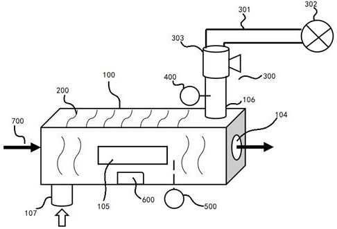
[0038] refer to figure 1 , an embodiment of the present invention provides a tracer PLIF calibration device under scramjet test conditions, including a closed cavity 100; the cavity 100 is provided with a heating module 200 for calibrating The gas in the cavity is heated and heated to realize the adjustment and control of the temperature in the cavity 100; the cavity 100 is connected with a pumping / inflating module 300, and the pressure in the cavity 100 is adjusted and controlled through the pumping / inflating module 300; the The cavity 100 is provided with a temperature sensor 500 and a ...


PUM


Abstract

The invention provides a scramjet tracing PLIF multi-parameter distribution measurement device and method. By constructing a combustion ramjet injection tracing PLIF multi-parameter distribution synchronous measurement device, a plurality of CCD cameras are used to obtain the simulated fuel injection conditions. The intensity ratio of the laser-induced fluorescence image obtained by the tracer PLIF image and the intensity calibration of the constant temperature and variable pressure image I 1 / I 2 with pressure P Relationship f ( P ), the ratio of laser-induced fluorescence image intensity obtained by image intensity calibration at constant pressure and temperature I 3 / I 4 with temperature T Relationship f ( T ), the image intensity of the laser-induced fluorescence image obtained by the image intensity calibration of the constant pressure, constant temperature and variable component concentration I 5 and the concentration of the tracer substance in the cavity n Relationship f ( n ), the quantitative distribution results of the injection fuel concentration, pressure and temperature field of the scramjet can be obtained directly. The invention can realize the synchronous measurement of components, pressure and temperature fields in the scramjet engine.

Description

technical field [0001] The invention relates to the technical field of scramjets, in particular to a scramjet tracing PLIF multi-parameter distribution measuring device and method. Background technique [0002] It is of great significance to realize the quantitative measurement of the injection fuel concentration, temperature and pressure field of the scramjet engine for revealing the fuel injection mixing and transportation process inside the engine and exploring the fuel mixing enhancement mechanism. The traditional gas analysis method can realize quantitative analysis of gas components and temperature after gas contact sampling, but this contact measurement method is limited by complex and severe engine experimental conditions (high speed, high turbulence), so its application scope is limited. At the same time, only single-point measurement can be performed. [0003] Laser-induced fluorescence (PLIF) technology based on molecular tracer is a relatively advanced measureme...

Claims


Application Information

Patent Timeline
Patent Type & Authority Patents(China)
IPC IPC(8): G01M15/14G06T7/00G06V10/143
CPCG01M15/14G06T7/0004G06T2207/10064G06T2207/30108Y02T90/00
Inventor 闫博孙明波朱家健孙永超汪洪波田轶夫
Owner NAT UNIV OF DEFENSE TECH
Why Eureka
Try Eureka