[0023] The technical solutions in the embodiments of the present invention will be clearly and completely described below with reference to the accompanying drawings in the embodiments of the present invention. Obviously, the described embodiments are only a part of the embodiments of the present invention, rather than all the embodiments. Based on the embodiments of the present invention, all other embodiments obtained by those of ordinary skill in the art without creative efforts shall fall within the protection scope of the present invention.
[0024] Specific examples are given below.
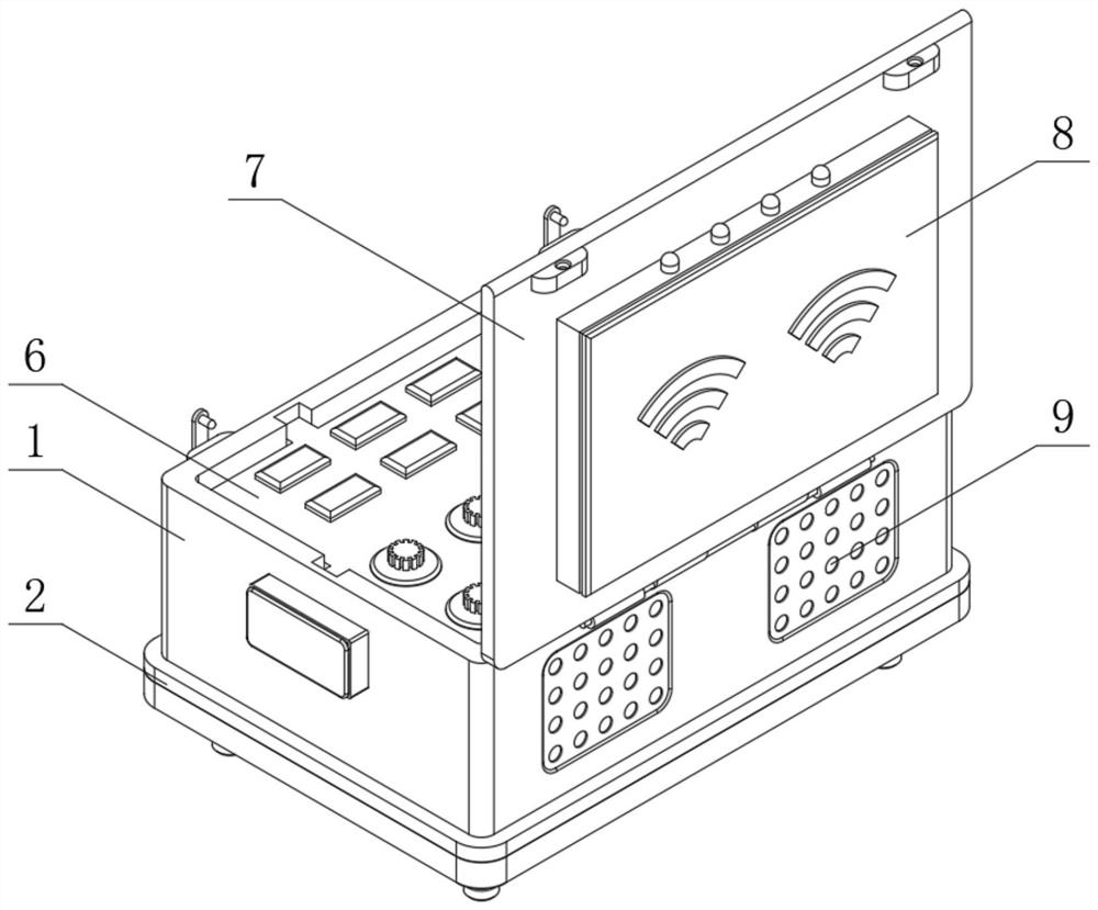
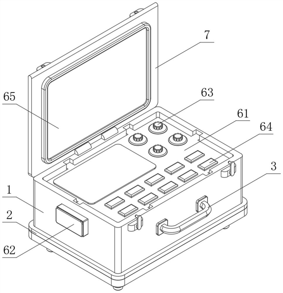
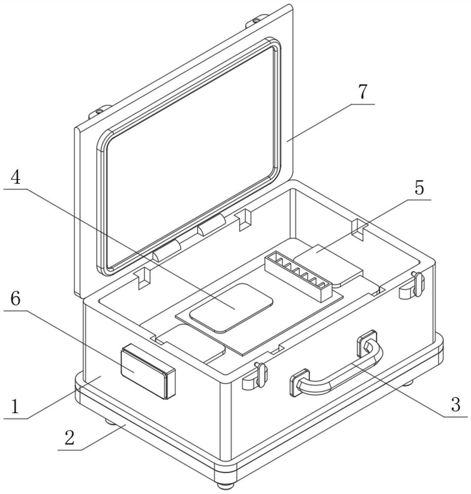
[0025] see Figure 1-6 , an unmanned aerial vehicle swarm formation system, including a crash box 1, an insulation component 2, a cluster formation system body 4, an installation component 5, a control component 6, a protective box cover 7 and a signal box 8, and the bottom end face of the crash box 1 The insulation component 2 is fixedly installed, the inner bottom of the crash box 1 is provided with an installation component 5, and the inner side of the installation component 5 is installed with the cluster formation system body 4, and the inner top of the crash box 1 is installed with a control component 6, and the crash box A protective box cover 7 is installed on both sides of the top of the outer wall of 1 through hinges, one end of the protective box cover 7 is installed with a signal box 8, and the inside of the signal box 8 is fixedly installed with a reinforced antenna; the center of the end face of the crash box 1 is screwed The carrying handle 3 is fixedly installed, the top of the end face of the crash box 1 is fixed with a fixed buckle by screws, and the top of the end face of the protective box cover 7 is fixed with a fixed slot by screws, and the fixed buckle is inserted It is installed inside the fixed card slot, and the protective box cover 7 is fixedly installed on one end of the anti-collision box 1 through the fixed buckle and the fixed card slot, and the device is easily transported and moved by the carrying handle 3, which greatly improves the convenience of use. ; Both sides of the back end face of the crash box 1 are provided with heat dissipation holes 9, which can improve the heat dissipation effect inside the crash box 1;
[0026] The control assembly 6 includes a manipulator 61, a junction box 62, a sub-control switch 63, a main control switch 64 and a display 65. The manipulator 61 is fixedly installed on the inner top of the crash box 1, and the top end face side of the manipulator 61 is provided with several A sub-control switch 63 is provided, a main control switch 64 is provided on the other side of the top end face of the manipulator 61, a display 65 is fixedly installed on the end face of the inner wall of the protective box cover 7, and a junction box is fixedly installed in the center of both sides of the outer wall of the crash box 1 62, and the junction box 62 is electrically connected with the controller 61;
[0027] The insulating assembly 2 includes an insulating base 21, a dust cover 22, a folding seat 23, a supporting top seat 24, a load-bearing column 25 and an anti-skid foot pad 26. The insulating base 21 is fixedly installed on the bottom end face of the crash box 1, and the bottom of the insulating base 21 A dust cover 22 is fixedly installed at the edge of the end face, and a folding seat 23 is fixed and installed around the bottom end face of the insulating base 21 by screws, and a supporting top seat 24 is installed between the folding seats 23 through a rotating pin connection. A folding bump is fixedly installed on the outer side; a load-bearing column 25 is fixedly installed on the bottom end face of the support top seat 24, and an anti-skid foot pad 26 is fixed on the bottom end face of the load-bearing column 25, and the anti-skid effect can be improved by the anti-skid foot pad 26; The insulating assembly 2 can support the crash box 1, and the insulating effect is good;
[0028] The installation assembly 5 includes a buffer plate 51 , a coil spring 54 , a fixed card frame 55 , a locking screw 56 and a fixed partition plate 57 . The buffer plate 51 is arranged on the inner bottom of the crash box 1 , and the cluster formation system body 4 is located on the buffer plate 51 . Above the top of the bumper plate 51, a number of coil springs 54 are fixedly installed on the bottom end face of the buffer plate 51, and the bottom end of the coil spring 54 is fixedly connected to the bottom inner wall of the crash box 1, and both sides of the top end face of the buffer plate 51 are plugged A fixed card frame 55 is installed, the top inner end face of the fixed card frame 55 is connected with the top end face of the cluster formation system body 4, and one end of the bottom of the fixed card frame 55 penetrates the buffer plate 51, and the two fixed card frames 55 are connected and installed with The locking screw 56 and the fixed partition plate 57 are fitted and installed on the bottom end face of the buffer plate 51, and the top end of the locking screw 56 is fitted and connected with the bottom end face of the buffer plate 51; both ends of the inner bottom of the crash box 1 are opened There are two buffer grooves 52 . Anti-separation blocks 53 are fixedly installed on both sides of the end face of the buffer plate 51 , and one end of the anti-separation blocks 53 is inserted and installed inside the buffer groove 52 . Internal sliding, so that the height of the buffer plate 51 can be adjusted;
[0029] The swarm formation system body 4 includes an unmanned aerial vehicle swarm formation formation generation module, an unmanned aerial vehicle swarm formation formation maintenance module, an unmanned aerial vehicle swarm formation formation transformation module and an unmanned aerial vehicle swarm formation formation obstacle avoidance module; The UAV swarm formation formation generation module connects multiple UAVs to complete the formation of the formation; through the UAV swarm formation formation maintenance module, the UAV formation can be maintained after the formation and set according to the system. The UAV swarm formation formation transformation module can transform the formation of the UAV into a formation; through the UAV swarm formation formation obstacle avoidance module, the UAV can make the UAV formation. When the swarm formation encounters obstacles, it can move to avoid obstacles.
[0030]The working principle of the present invention: when in use, the device can be transported to a suitable use position through the handling handle 3 outside the crash box 1, the crash box 1 is supported by the insulating assembly 2, and the crash box 1 is supported by the insulating base 21 and the dust-proof The cover 22 can make the crash box 1 have a good insulating effect, and the support top seat 24 can be rotated inside the folding seat 23, so that the bearing column 25 is in a vertical state, and the anti-skid foot pad 26 can support the bearing column 25. After the fixing slot on the outer side of the protective box cover 7 is separated from the fixing buckle on the outer side of the crash box 1, the protective box cover 7 is opened, and inside the crash box 1, the main unit 4 of the cluster formation system is fixedly installed in the The interior of the anti-collision box 1 enables the cluster formation system host 4, the control assembly 6 and the signal box 8 to control the drone cluster formation. On the top of the buffer plate 51, the top of the cluster formation system host 4 is fixed by the fixed card frame After attaching, attach the fixed partition 57 to the bottom end face of the buffer plate 51, and use the locking screw 56 and bolts to fix the two fixing brackets 55. When the crash box 1 shakes, the buffer plate 51 will be shaken. Squeeze the coil spring 54, so that the anti-separation block 53 on the outside of the buffer plate 51 slides inside the buffer groove 52, so that the coil spring 54 can have a good buffer effect on the buffer plate 51; connect the external equipment to the junction box 62. After that, through the sub-control switch 63 on the top of the controller 61, the UAV can be controlled individually, through the main control switch 64, the overall control of the UAV swarm formation can be performed, and the main unit 4 and the signal box 8 of the swarm formation system can transmit the signal Send it to the drone to control multiple drones to fly, so as to achieve cluster formation control, and the scene captured by the drone can be displayed through the display 65, which is convenient for displaying the emergency scene during emergency operations; The inside of the hit box 1 conducts heat dissipation.
[0031] The above description is only a preferred embodiment of the present invention, but the protection scope of the present invention is not limited to this. The equivalent replacement or change of the inventive concept thereof shall be included within the protection scope of the present invention.