Separating device for food processing
A separation device, food processing technology, applied in the processing of meat, poultry processing, application, etc., can solve the problems of waste, excessive chicken feet cut off, the position of the cutter cannot be accurately positioned, etc., to achieve the effect of reducing the amount of cutting
- Summary
- Abstract
- Description
- Claims
- Application Information
AI Technical Summary
Problems solved by technology
Method used
Image
Examples
Embodiment 1
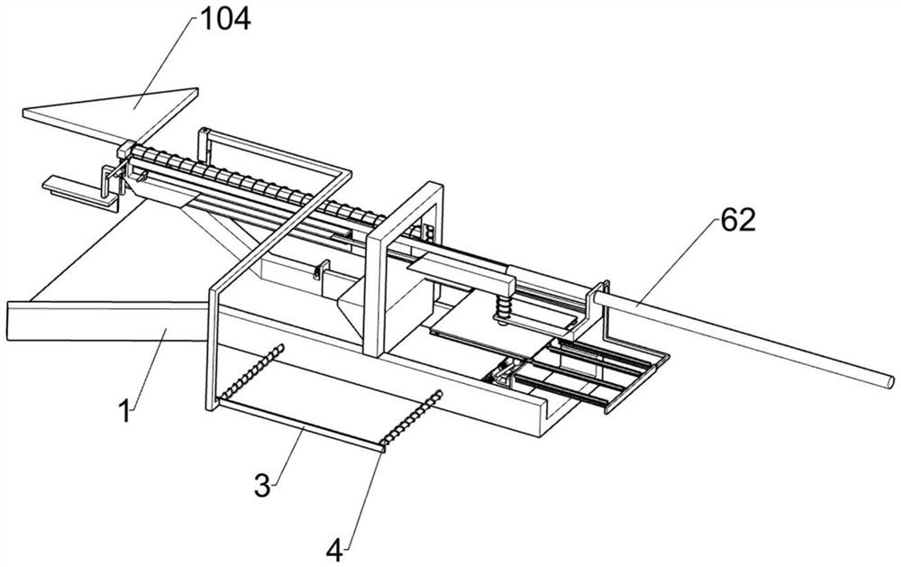
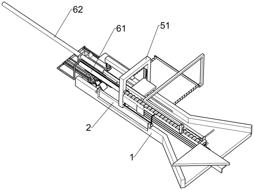
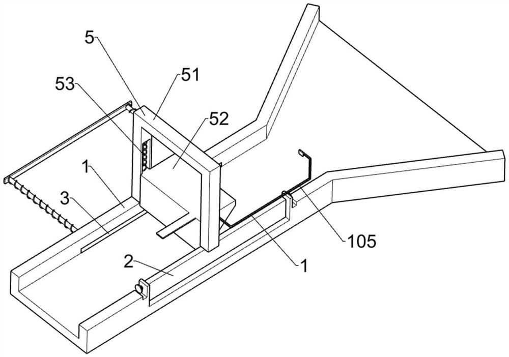
[0038] A separation device for food processing, such as Figure 1-8As shown, it includes a guide frame plate 1, a swing plate 2, a push rod 3, a compression spring 4, a chicken claw limit member 5, a drive member 6, a chicken claw nail chamfering member 7 and a push member 8, and the guide frame plate 1 A swinging plate 2 is rotatably connected by a torsion spring, a push rod 3 is slidably connected to the guide frame plate 1, and a pair of compression springs 1 4 are connected between the push rod 3 and the guide frame plate 1, and the push rod 3 is used to cut off the nail The completed chicken feet are pushed away. The guide frame plate 1 is provided with a chicken claw limit member 5, which is used to clamp the chicken feet. The chicken claw limit member 5 is provided with a driving member 6. The guide frame The plate 1 is provided with a chicken claw nail bevelling member 7, the chicken claw nail chamfering member 7 is used for chamfering the chicken claw nail, and the dr...
Embodiment 2
[0044] On the basis of Example 1, as Figure 9-11 As shown, it also includes an automatic conveying part 9, the guide frame 51 is provided with an automatic conveying part 9, and the automatic conveying part 9 includes a guide groove frame 91, a cross bar 92, a short movable bar 93, a return spring 94, a belt guide The slot limit column 941, the movable column 95, the return spring two 96, the push seat 97, the inclined limit plate 98, the limit spring 99, the push bar 910, the connecting spring one 911 and the oblique long rod 912, the guide frame 51 passes through A guide groove frame 91 is fastened to the bolts. The guide groove frame 91 is used to guide the moving path of the movable column 95. The guide frame 51 is provided with a cross bar 92. The cross bar 92 is located above the guide groove frame 91, and the cross bar 92 slides on it. A short movable bar 93 is connected with the short movable bar 93, and a return spring 94 is connected between the short movable bar 93...
Embodiment 3
[0046] On the basis of Example 2, as Figure 9 and Figure 12 As shown, it also includes a push-off member 10, the push-off member 10 is provided on the push rod 3, and the push-off member 10 includes a connecting rod 101, an inclined plane rod 102, a connecting spring two 103, a triangle plate 104 and a limit rod frame 105, A connecting rod 101 is fixedly connected to the push rod 3 by means of bolts. The connecting rod 101 is slidably connected with an inclined plane rod 102. A connecting spring two 103 is connected between the inclined plane rod 102 and the connecting rod 101, and a triangular plate 104 is welded on the short movable bar 93. , the single-slope lower pressing block 52 is provided with a limit rod frame 105 , and the limit rod frame 105 is slidably connected with the guide groove frame 91 .
[0047] The factory-processed and pre-treated chicken feet are conveyed to the top side of the guide frame plate 1 by other conveying devices. The appearance, shape and ...
PUM
 Abstract
Description
Claims
Application Information
 - R&D
- Intellectual Property
- Life Sciences
- Materials
- Tech Scout
- Unparalleled Data Quality
- Higher Quality Content
- 60% Fewer Hallucinations
Browse by: Latest US Patents, China's latest patents, Technical Efficacy Thesaurus, Application Domain, Technology Topic, Popular Technical Reports.
© 2025 PatSnap. All rights reserved.Legal|Privacy policy|Modern Slavery Act Transparency Statement|Sitemap|About US| Contact US: help@patsnap.com


