High-lift-drag-ratio wind turbine airfoil profile under large attack angle and design method of high-lift-drag-ratio wind turbine airfoil profile

A technology with high lift-to-drag ratio and design method, which is applied to wind turbines, wind turbines, mechanical equipment and other directions that are consistent with the wind direction, can solve the problem of low aerodynamic efficiency of vertical axis wind turbines, reduce the economic benefits of wind turbine rotors, and is easy to appear. Airflow separation and other issues, to achieve the effect of improving wind energy absorption efficiency, small resistance and small resistance

Pending Publication Date: 2022-06-07
XI AN JIAOTONG UNIV
View PDF0 Cites 0 Cited by
  • Summary
  • Abstract
  • Description
  • Claims
  • Application Information

AI Technical Summary

Problems solved by technology

[0005] The purpose of the present invention is to provide a high-lift-drag ratio wind turbine airfoil and its design method at a large angle of attack, which solves the problem of easy airflow separation at a high angle of attack, thereby reducing the lift coefficient, increasing the drag coefficient, and reducing the airflow. The economic benefits of wind turbine wind turbines have been compromised, and the aerodynamic efficiency of vertical axis wind turbines is not high at low wind speeds.

Method used


Image

  • High-lift-drag-ratio wind turbine airfoil profile under large attack angle and design method of high-lift-drag-ratio wind turbine airfoil profile
  • High-lift-drag-ratio wind turbine airfoil profile under large attack angle and design method of high-lift-drag-ratio wind turbine airfoil profile
  • High-lift-drag-ratio wind turbine airfoil profile under large attack angle and design method of high-lift-drag-ratio wind turbine airfoil profile

Examples


Embodiment 1

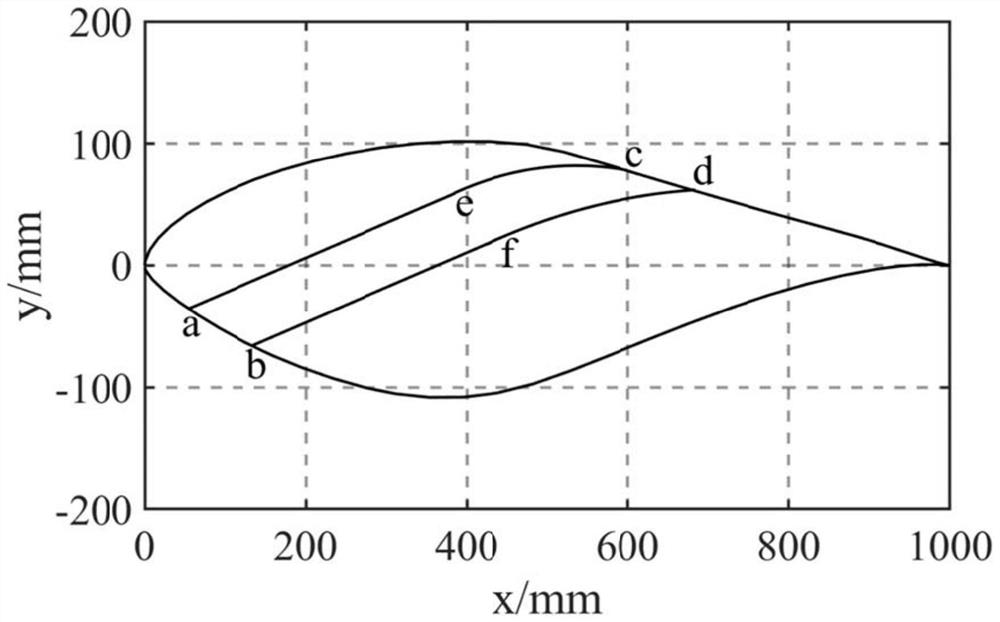
[0050] In the high lift-to-drag ratio wind wing model provided by the present invention, the front section of the slit is linear, and the rear section is circular. ae and bf are two line segments, ec and fd are two arcs, and the chord length of the reference airfoil profile is C, where a x =0.05C, b x =0.13C, c x =0.59c,d x =0.66C, the width of ab is 0.08C, ae is parallel to bf, the lateral distance of ae is 0.34C, bf=0.32C, the angle between ae and the x-axis is 16°, ec is an arc with a radius of 0.52Cmm, and Tangent to the upper airfoil, and fd is an arc with a radius of 0.41C and a cd width of 0.07C. It is named S809-1 after this.

Embodiment 2

[0052] In the high lift-to-drag ratio wind wing model provided by the present invention, the front section of the slit is linear, and the rear section is circular. ae and bf are two line segments, ec and fd are two arcs, and the chord length of the reference airfoil profile is C, where a x =0.05C, b x =0.12C, c x =0.55C, d x =0.63C, the width of ab is 0.07C, ae is parallel to bf, the lateral distance of ae is 0.34C, bf=0.32C, the angle between ae and the x-axis is 10°, ec is an arc with a radius of 0.51Cmm, and Tangent to the upper airfoil, fd is an arc with a radius of 0.41C, and the width of cd is 0.07C, denoted as S809-4.

Embodiment 3

[0054] In the high lift-to-drag ratio wind wing model provided by the present invention, the front section of the slit is linear, and the rear section is circular. ae and bf are two line segments, ec and fd are two arcs, and the chord length of the reference airfoil profile is C, where a x =0.08C, b x =0.18C, c x =0.65C, d x =0.75C, the width of ab is 0.1C, ae is parallel to bf, the lateral distance of ae is 0.34C, bf=0.32C, the angle between ae and the x-axis is 20°, ec is an arc with a radius of 0.53Cmm, and Tangent to the upper airfoil, fd is an arc with a radius of 0.42C, and the width of cd is 0.1C, denoted as S809-5.

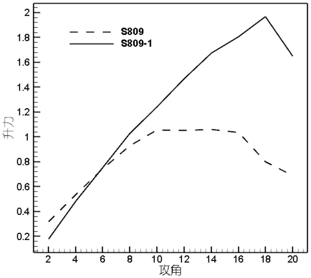
[0055] from Figure 14 It can be seen that compared with the reference airfoil, the slotted airfoil will have a better lift-drag ratio, but the position and shape of the slot are the key.

[0056] The advantages of a wind turbine airfoil with a high lift-to-drag ratio of the present invention are verified by comparing the following different inflow an...


PUM

PropertyMeasurementUnit
Angleaaaaaaaaaa

Abstract

The invention belongs to the technical field of wind power generation, and particularly relates to a design method of a high lift-drag ratio wind turbine airfoil under a large attack angle, which is described by a forming process as follows: projecting a reference airfoil profile in an XY coordinate system to obtain a reference airfoil profile, and overlapping a leading edge point of the reference airfoil profile with a coordinate origin to obtain a reference airfoil profile; a slot is formed in the reference airfoil profile; selecting two points on the lower wing surface as the inlet of the slot, and recording as a point a and a point b; selecting two points on the upper wing surface as outlets of the slot, and recording the two points as a point c and a point d; a point e is selected between the point a and the point c, and a point f is selected between the point b and the point d; the aec and the bfd form a slotted shape, and a channel is formed in the middle of the airfoil; ae and bf are straight lines, ec and fd are arcs, and ae is parallel to bf. And a larger stall angle of attack and smaller resistance are realized, and the lift-drag ratio under the large angle of attack is obviously improved, so that the wind energy absorption efficiency of the wind wheel of the wind generating set is improved.

Description

technical field [0001] The invention belongs to the technical field of wind power generation, and in particular relates to a high lift-to-drag ratio wind turbine airfoil and a design method thereof under a large attack angle. Background technique [0002] For the geometric shape of the wind blade, the airfoil is the "gene" of the blade, and its aerodynamic performance directly affects the aerodynamic performance of the wind turbine blade. Therefore, the design of the aerodynamic shape of the wind turbine blade of the wind turbine cannot be separated from the airfoil design. Before the 1980s, the airfoils of wind turbines often used aviation airfoils. However, aviation airfoils are usually designed under the condition of subsonic speed, and the aerodynamic performance cannot be effectively guaranteed under low speed conditions. In addition, there are disadvantages of small thickness and inability to meet structural requirements. At the same time, the airfoil stalls at high an...

Claims


Application Information

Patent Timeline
IPC IPC(8): F03D1/06F03D80/00
CPCF03D1/0633F03D1/0675F03D80/00Y02E10/72Y02E10/74
Inventor 张扬杨光宇曾鑫磊胡澜翔
Owner XI AN JIAOTONG UNIV
Why Eureka
Try Eureka