Eureka AIR delivers breakthrough ideas for toughest innovation challenges, trusted by R&D personnel around the world.

Non-metal carbon fiber full-winding high-pressure hydrogen storage bottle inner container bottle opening structure

A carbon fiber, non-metallic technology, applied in the field of non-metallic carbon fiber fully wound high-pressure hydrogen storage bottle liner bottle mouth structure, can solve the problems of inconvenient sealing performance, inconvenient and stable clamping installation, etc., to avoid unstable and stable fixation Simple installation and operation

Pending Publication Date: 2022-06-07
广东青禾能源技术有限公司
View PDF0 Cites 0 Cited by
  • Summary
  • Abstract
  • Description
  • Claims
  • Application Information

AI Technical Summary

Problems solved by technology

[0005] The purpose of the present invention is to provide a non-metallic carbon fiber fully wound high-pressure hydrogen storage bottle liner mouth structure, in order to solve the above-mentioned background technology, the existing inner liner bottle mouth structure is inconvenient for convenient and stable clamping installation, and at the same time it is not convenient It is convenient to use the pressure of the gas to improve the sealing performance

Method used

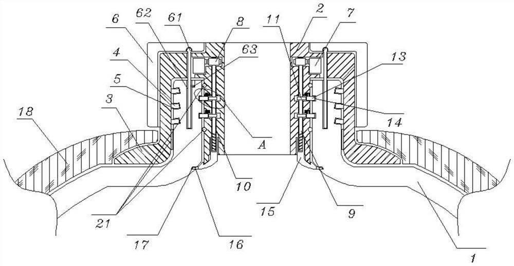

Image

  • Non-metal carbon fiber full-winding high-pressure hydrogen storage bottle inner container bottle opening structure
  • Non-metal carbon fiber full-winding high-pressure hydrogen storage bottle inner container bottle opening structure
  • Non-metal carbon fiber full-winding high-pressure hydrogen storage bottle inner container bottle opening structure

Examples


Embodiment 1

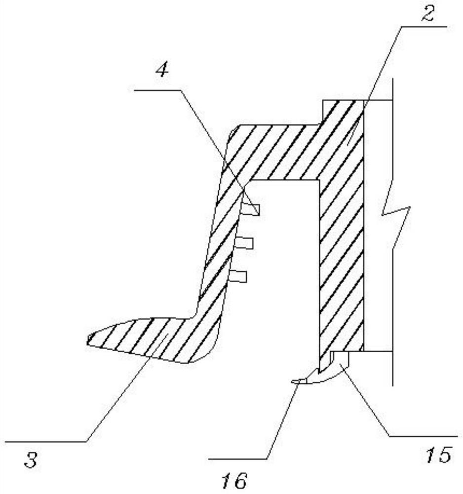
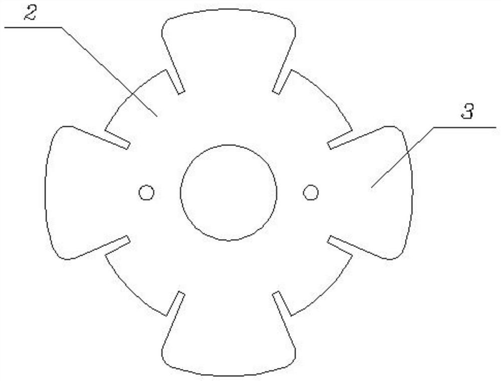
[0033] see Figure 1-6, including a plastic bottle mouth 1, the end of the plastic bottle mouth 1 is sleeved with a metal kit 2, and the outer side of the metal kit 2 is connected with a raised edge 3, and the raised edge 3 is located outside the top of the plastic bottle mouth 1, The contact positions of the metal sleeve 2 and the raised edge strip 3 and the plastic bottle mouth 1 are all provided with a sealing gasket 21, and the plastic bottle opening 1 and the metal sleeve 2 and the raised edge strip 3 are all wound with a carbon fiber winding layer 18; also includes : the fixing sleeve 6, the fixing sleeve 6 is threadedly sleeved on the outer side of the top of the metal sleeve 2, and the initial position of the fixing sleeve 6 is located above the raised edge strip 3, and the inner wall of the raised edge strip 3 is fixed with an outer fixing strip 4, and The outer fixing strip 4 is located in the outer fixing groove 5, and the outer fixing groove 5 is opened on the oute...

Embodiment 2

[0035] see figure 1 and Figure 4-7 , the sealing cover 15, the sealing cover 15 is threadedly sleeved at the bottom position of the vertical rod 9, and the bottom end of the sealing cover 15 is located below the metal sleeve 2, the bottom edge of the sealing cover 15 is fixed with a positioning convex strip 16, and the positioning convex One end of the strip 16 is located in the locking groove 17, and the locking groove 17 is opened on the inner wall of the arc section below the plastic bottle mouth 1, the sealing cover 15 is vertically fit and slides in the vertical groove 10 through the vertical rod 9, and the sealing cover 15 The bottom of the metal sleeve 2 has a horn-shaped structure, which is matched with the bottom of the metal sleeve 2 and the arc end of the inner wall of the plastic bottle mouth 1, and the bottom edge of the metal sleeve 2 has a convex structure design. , and the concave-convex match between the positioning convex strip 16 and the locking groove 17,...


PUM


Abstract

The nonmetal carbon fiber full-winding high-pressure hydrogen storage bottle inner container bottle opening structure comprises a plastic bottle opening, the end of the plastic bottle opening is sleeved with a metal sleeve piece, and sealing gaskets are arranged at the contact position of the metal sleeve piece and the plastic bottle opening and the contact position of a protruding edge strip and the plastic bottle opening; the device further comprises a fixing sleeve, the fixing sleeve is arranged on the outer side of the top of the metal sleeve in a threaded and sleeving mode, an outer fixing strip is fixed to the inner wall of the protruding note, a gear ring is movably installed in the top of the metal sleeve in an embedded mode, a vertical rod is fixedly installed in a gear, and an inner fixing rod is connected to the side of the interior of the metal sleeve in a penetrating mode through a spring. And the sealing cover is arranged at the bottom position of the vertical rod in a threaded and sleeving manner. According to the nonmetal carbon fiber full-winding high-pressure hydrogen storage bottle inner container bottle opening structure, sealing and fixing of the metal sleeve piece and the plastic bottle opening can be achieved by rotating the fixing sleeve, and meanwhile the sealing effect can be enhanced through the sealing cover by means of internal air pressure.

Description

technical field [0001] The invention relates to the technical field of high-pressure gas storage bottles, in particular to a non-metallic carbon fiber full-wound high-pressure hydrogen storage bottle liner bottle mouth structure. Background technique [0002] High-pressure gas storage cylinder is a container for storing high-pressure gas. The inner liner is widely used due to its light weight and high strength, but the strength of the plastic inner liner seal is low, and it is usually necessary to add a metal bottle mouth for installation to ensure the strength of the bottle mouth, but the existing liner bottle The mouth structure has the following problems in use: [0003] In the bottle mouth structure of the inner tank, in order to ensure the installation, tightening and sealing, it is usually necessary to use a clamping structure, but the existing bottle mouth structure of the inner tank usually adopts the concave-convex matching for direct clamping, which requires a lar...

Claims


Application Information

Patent Timeline
Patent Type & Authority Applications(China)
IPC IPC(8): F17C1/00F17C13/06
CPCF17C1/00F17C13/06F17C2205/0305Y02E60/32
Inventor 梅龙伟
Owner 广东青禾能源技术有限公司
Why Eureka
Eureka Blog
Learn More