
Evaporation phase change heat transfer component based on gel decoupling driving and application thereof

A technology of heat transfer components and gel, which is applied in the field of heat transfer, can solve the problems of limiting the capillary material's liquid absorption capacity and maximum heat flux, and achieve the effects of improving liquid absorption and heat transfer capacity, large evaporation area, and expanding the scope of application

Active Publication Date: 2022-06-07
WUHAN UNIV
View PDF7 Cites 0 Cited by
  • Summary
  • Abstract
  • Description
  • Claims
  • Application Information

AI Technical Summary

Problems solved by technology

Therefore, the coupling relationship between the two will limit the capillary material's liquid absorption capacity and the maximum heat flux it can withstand, which is also the core technical bottleneck of the liquid absorption and heat transfer of evaporative phase change heat transfer components.

Method used


Image

  • Evaporation phase change heat transfer component based on gel decoupling driving and application thereof
  • Evaporation phase change heat transfer component based on gel decoupling driving and application thereof
  • Evaporation phase change heat transfer component based on gel decoupling driving and application thereof

Examples


preparation example Construction

[0033] The preparation method of the evaporative phase change heat transfer member 10 is as follows:

[0034] 1) The surface of the capillary core 11 is modified with a functional group that can be chemically bonded to the hydroxyethyl methacrylate hydrogel 12, and the functional group can be a functional group with an unsaturated chemical bond, such as a methacrylate functional group;

[0035] 2) Pour the hydroxyethyl methacrylate hydrogel 12 stock solution into the mold, and adopt the optical method, thermal method or other method to make the hydrogel stock solution semi-crosslinking;

[0036] 3) The semi-solidified hydroxyethyl methacrylate hydrogel 12 is attached to the capillary core 11 , and after lamination, the hydrogel is completely cross-linked to obtain the evaporative phase change heat transfer member 10 .

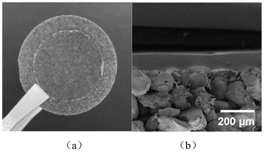
[0037] An example of the obtained evaporative phase change heat transfer member 10 is shown in the figure figure 2 As shown in (a), the upper layer is the hy...

Embodiment 3

[0043] like Figure 4 As shown, the evaporative phase change heat transfer member 30 based on gel decoupling driving provided in the third embodiment includes a substrate 31 , a group of microgrooves 32 , and a hydrogel film 33 . The microgroove group 32 is formed on the base 31 and extends from the cold end to the hot end, and includes a plurality of elongated channels parallel to each other. The microgroove group 32 is located at the return inlet of the cold end and communicates with the heat transfer medium 34 (water). The hydrogel film 33 covers all the micro-grooves 32 except for the return inlet, and closely adheres to other parts (outer surfaces) of the substrate 31 except for the grooves.

[0044] When the evaporative phase change heat transfer member 30 is used for heat dissipation, the hydrogel film 33 absorbs water 34 from the microgroove group 32, the water 34 absorbs heat and evaporates into the environment mainly at the hot end, and then the water vapor condenses...


PUM


Abstract

According to the evaporation phase change heat transfer component based on gel decoupling driving and the application of the evaporation phase change heat transfer component, the antagonism relation between the liquid absorption capacity and the flow resistance in an existing heat transfer device can be decoupled, driving force is provided through the large-area gel layer located on the surface of the capillary material, and therefore the liquid absorption and heat transfer capacity and efficiency of the heat transfer component are practically improved. The invention provides an evaporation phase change heat transfer component based on gel decoupling driving, which is characterized by comprising a capillary material layer for providing a transport channel of a heat transfer working medium; and the surface gel film layer serves as a heat transfer medium evaporation interface, is attached to the outer surface of the capillary material layer, does not fill the transportation channel and is used for absorbing and driving the heat transfer working medium, so that the heat transfer working medium is driven and conveyed to the hot end along the transportation channel.

Description

technical field [0001] The invention belongs to the technical field of heat transfer, and in particular relates to an evaporative phase-change heat transfer component driven by gel decoupling and its application. Background technique [0002] Evaporative phase change heat transfer components have a wide range of applications in the field of heat dissipation, such as capillary wicks in heat pipes, channels, and capillary structures for sweat cooling at engine nozzles. In the process of heat transfer, the capillary material can provide the Laplace force required for evaporating the phase change interface and pumping the phase change working medium, and has the advantages of simple structure, no energy consumption, economical and environmental protection, and the like. Among them, the larger the Laplace force, the higher the evaporation flux that can be loaded, or the longer the flow channel that can be loaded. The maximum Laplace force of the capillary material depends on the...

Claims


Application Information

Patent Timeline
Patent Type & Authority Applications(China)
IPC IPC(8): F28D15/04
CPCF28D15/046Y02E60/14
Inventor 刘抗刘禹希庾泽华徐诗浩程鹏
Owner WUHAN UNIV
Learn More