Display glass preparation device with adjustable reflectivity in frame area

A technology for preparing device and reflectivity, which is applied to computer monitor casings, instruments, computing, etc., can solve problems such as poor reflectivity of protective glass, and achieve the effect of avoiding local lighting, improving flatness, and ensuring completion.

Pending Publication Date: 2022-06-07
华玻视讯(珠海)科技有限公司
View PDF0 Cites 0 Cited by
  • Summary
  • Abstract
  • Description
  • Claims
  • Application Information

AI Technical Summary

Problems solved by technology

[0005] In order to overcome the disadvantage that the existing cover glass only performs simple ink printing and does not control the flatness of the ink layer, resulting in extremely poor reflectivity of the cover glass, the present invention provides a display glass preparation device with adjustable reflectivity in the frame area

Method used


Image

  • Display glass preparation device with adjustable reflectivity in frame area
  • Display glass preparation device with adjustable reflectivity in frame area
  • Display glass preparation device with adjustable reflectivity in frame area

Examples


Embodiment 1

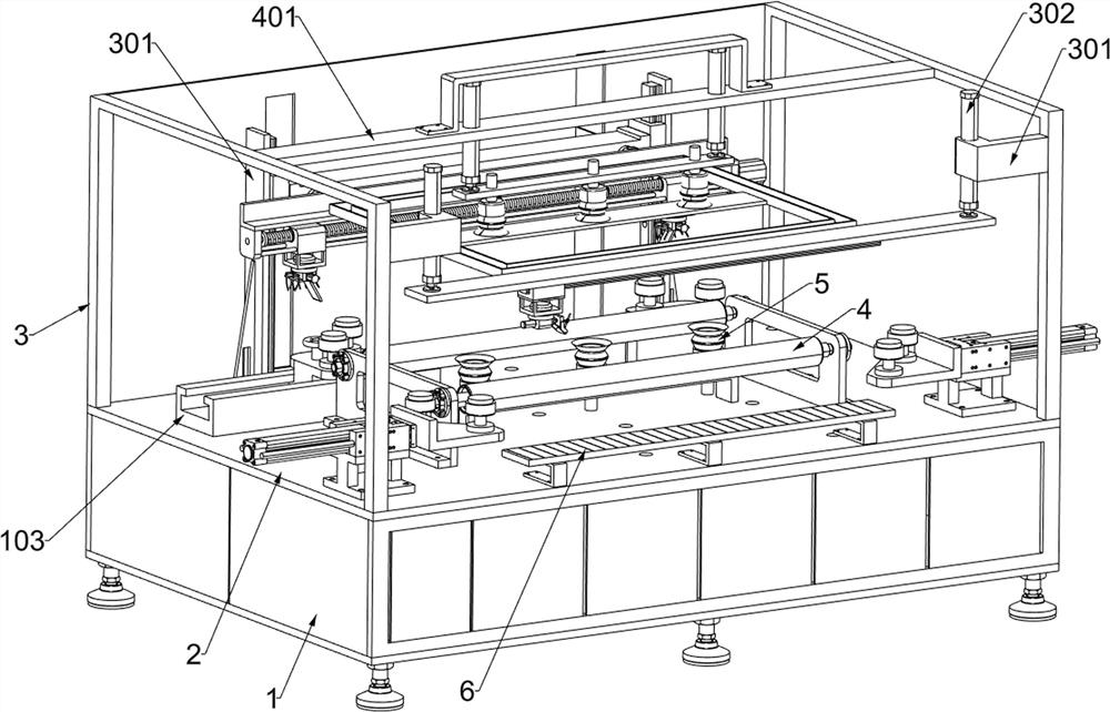
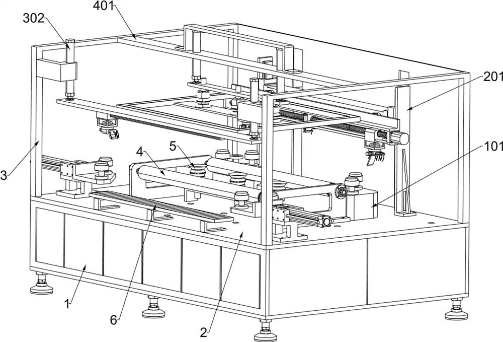
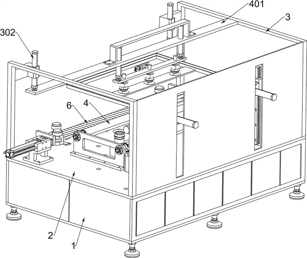
[0033] A display glass preparation device with adjustable bezel area reflectivity, such as figure 1 , figure 2 and image 3 As shown, it includes a frame 1, a workbench 2, a fixed frame 3, a guide roller assembly 4, a linear illumination lamp group 6, a positioning system, a push printing system and a repair system; the upper surface of the frame 1 is fixed with a workbench 2 ; The left part of the upper surface of the worktable 2 and the right part of the upper surface are each fixed with a fixed frame 3; the middle part of the upper surface of the worktable 2 is fixed with a guide roller assembly 4; Group 6; a positioning system is connected to the upper surface of the worktable 2, and the positioning system is located on the outer side of the guide roller assembly 4; a push printing system is connected to the rear of the upper surface of the worktable 2; system.

[0034] It also includes a first suction cup 5 ; three first suction cups 5 are installed in the middle of t...

Embodiment 2

[0037] On the basis of Example 1, as figure 1 , Figure 4 and Figure 5 As shown, the positioning system includes a first support base 101, a first rotating clamping column 102, a straight slide rail 103, a moving block 104, a positioner 105, a second rotating clamping column 106, a first supporting block 107, a first electric telescopic 108, the second supporting seat 109 and the third rotating clamping column 1010; the first supporting seat 101 is welded to the right part of the upper surface of the table 2, and the first supporting seat 101 is located behind the guide roller assembly 4; the first supporting seat 101 The upper part is rotatably connected with two first rotating clamping columns 102; the upper surface of the worktable 2 is fixed with a straight slide rail 103, and the straight slide rail 103 is located on the left side of the first support base 101; the straight slide rail 103 is slidably connected with a mobile Block 104; the upper part of the moving block...

Embodiment 3

[0043] On the basis of Example 2, as figure 1 , Figure 4 , Image 6 , Figure 7 and Figure 8 As shown, the push printing system includes a first support plate 201, a first electric slide rail 202, a first electric slider 203, a fixed beam 204, a second electric telescopic piece 205, a first support frame 206, a servo motor 207, a bidirectional The screw rod 208, the limit rod 209, the first fixed block 2010, the third electric telescopic piece 2011, the second support plate 2012, the first suction pipe 2013 and the silk screen assembly 2014; the upper surface of the table 2 is fixed with two symmetrical Each of the two first support plates 201 is bolted with a first electric slide rail 202; each of the two first electric slide rails 202 is slidably connected with a first electric slider 203; two A fixed beam 204 is fixed between the opposite sides of the first electric slider 203; the fixed beam 204 is fixed with two symmetrical second electric telescopic parts 205; The...


PUM


Abstract

The invention relates to the field of display screen glass preparation, in particular to a display glass preparation device with adjustable frame area reflectivity. The technical problem that existing protective glass is only subjected to simple ink printing, the flatness of an ink layer cannot be controlled, and the reflectivity of the protective glass is extremely poor is solved. According to the technical scheme, the display glass preparation device with the adjustable reflectivity in the frame area comprises a rack, a workbench, a push printing system and the like; a workbench is fixedly connected to the upper surface of the rack. A printing system is connected to the rear portion of the upper surface of the workbench. Strict ink printing is performed on the coating film of the frame area of the protective glass, and meanwhile, the flatness of the whole ink layer is improved by adopting an edge traction mode in the printing process, so that the reflectivity of the whole frame area is kept consistent, local brightening is avoided, and the service life of the protective glass is prolonged. A small amount of printing ink is dropped on the missing part of the printing ink layer in a liquid dropping mode, the printing ink is flattened, meanwhile, a small amount of redundant printing ink is sucked away, and the completeness of a protective glass frame area is guaranteed.

Description

technical field [0001] The invention relates to the field of display glass preparation, in particular to a display glass preparation device with adjustable reflectivity of a frame area. Background technique [0002] When the display device is on the screen, both the display area and the surrounding non-display area appear black, but in most cases, the display area and the surrounding non-display area have different reflectivity to visible light, resulting in a certain chromatic aberration between the border area and the display area of ​​the display. , can not meet the needs of consumers with extreme requirements. [0003] Existing large-scale display devices with touch function all need to paste a protective glass on the outer surface of the display module. The coating quality of the ink layer in the frame area after the alloy film is plated determines the integrated black effect of the display area and the frame area when the display is closed, and the existing protective...

Claims


Application Information

Patent Timeline
IPC IPC(8): G06F1/16
CPCG06F1/1603
Inventor 冯宪轮
Owner 华玻视讯(珠海)科技有限公司
Why Eureka
Try Eureka