Conductive wheel of superconducting film preparation equipment and operation method of conductive wheel

A superconducting film and conductive wheel technology, applied in the field of conductive wheels, can solve the problems of reduced production efficiency, loose conductive wheels, inconvenient disassembly and assembly, etc., and achieve the effects of improving service life, convenient installation and disassembly, and convenient disassembly and maintenance.

Active Publication Date: 2022-06-07
HUAIYIN TEACHERS COLLEGE
View PDF7 Cites 2 Cited by
  • Summary
  • Abstract
  • Description
  • Claims
  • Application Information

AI Technical Summary

Problems solved by technology

[0003] However, when the traditional conductive wheel is installed and used, most of the current is transmitted through the contact between the brush and the conductive shaft. The contact area between the brush and the conductive wheel is large, and the friction is large, resulting in serious wear and frequent replacement, which reduces the Production efficiency, and with the increase of friction, the current resistance becomes larger, which affects the normal transmission of current. At the same time, after the brush is installed, it is inconvenient to replace the conductive wheels of different sizes for current transmission, and the replacement is cumbersome. Bolts are usually used to connect with the conductive shaft, which is easy to cause loosening after the conductive wheel rotates for a long time, and subsequent disassembly is not convenient

Method used


Image

  • Conductive wheel of superconducting film preparation equipment and operation method of conductive wheel
  • Conductive wheel of superconducting film preparation equipment and operation method of conductive wheel
  • Conductive wheel of superconducting film preparation equipment and operation method of conductive wheel

Examples


Embodiment Construction

[0037] In order to make it easy to understand the technical means, creation features, achieved goals and effects of the present invention, the present invention will be further described below with reference to the specific embodiments.

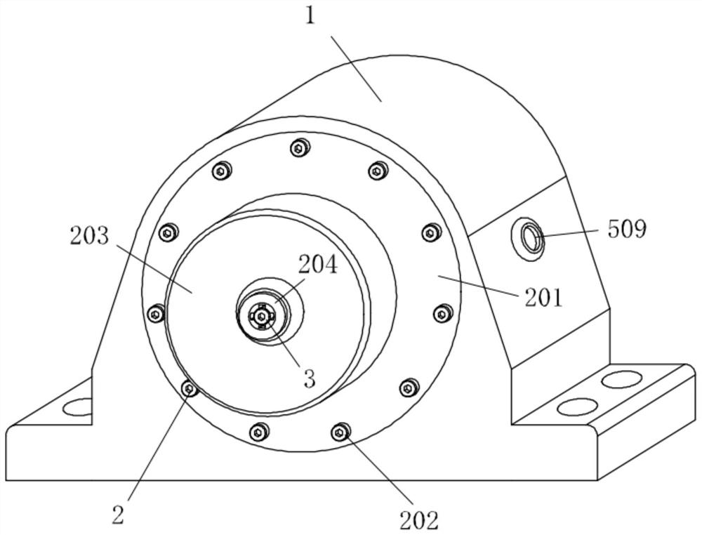
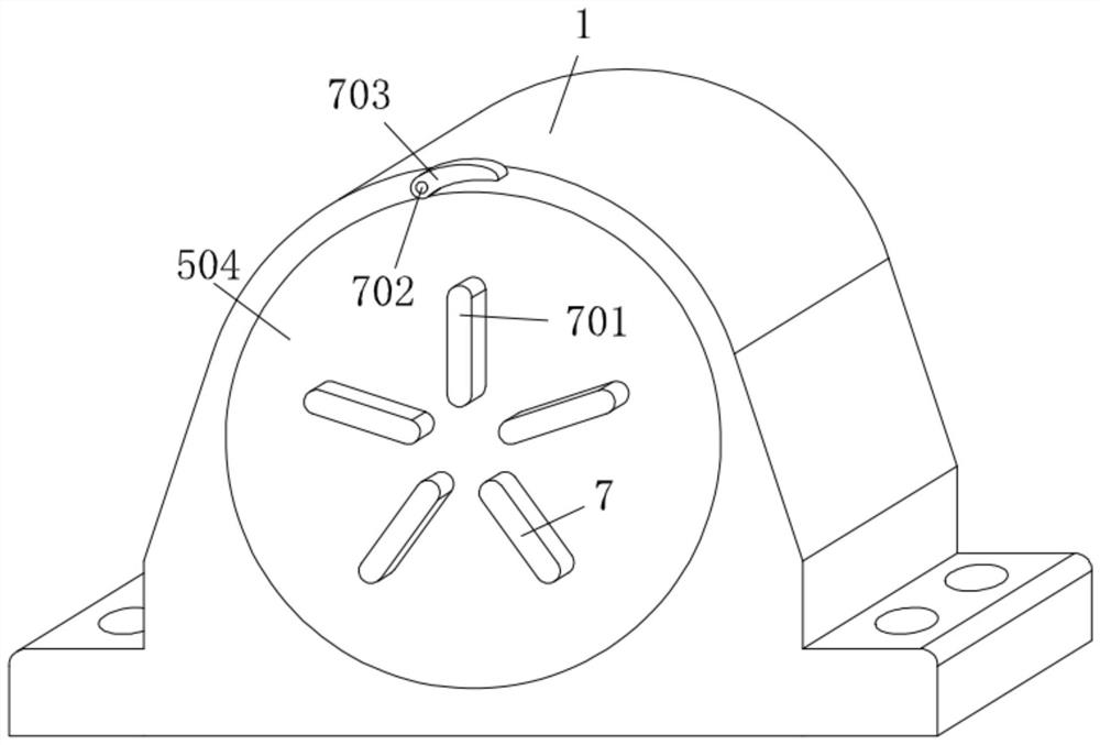
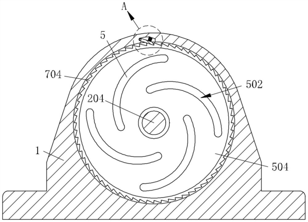
[0038] like Figure 1-Figure 10 As shown, the conductive wheel of a superconducting thin film preparation equipment according to the present invention includes a mounting seat 1, a rotating mechanism 2 is mounted on the mounting seat 1, a fastening mechanism 4 is mounted on the rotating mechanism 2, and the A driving mechanism 3 is connected to the rotating mechanism 2 , a conducting mechanism 5 is mounted inside the mounting base 1 , a control mechanism 7 is mounted on the conducting mechanism 5 , and a dismounting mechanism 6 is connected to the conducting mechanism 5 .

[0039] Specifically, the rotating mechanism 2 includes a support plate 205, and the support plate 205 is installed inside the mounting seat 1. The support plate 205 is in ...


PUM


Abstract

The invention relates to the technical field of conductive wheels, in particular to a superconducting film preparation equipment conductive wheel and an operation method thereof.The superconducting film preparation equipment conductive wheel comprises a mounting base, a rotating mechanism is mounted on the mounting base, a fastening mechanism is mounted on the rotating mechanism, a driving mechanism is connected to the rotating mechanism, a conductive mechanism is mounted in the mounting base, and the fastening mechanism is connected to the driving mechanism. The conductive mechanism is provided with a control mechanism, and the conductive mechanism is connected with a dismounting device; through installation of the rotating mechanism and the installation base, the superconducting thin film conveying guiding effect is facilitated, through cooperation of the fastening mechanism and the driving mechanism, the rotating mechanism can be conveniently installed and disassembled, operation is convenient, follow-up maintenance is facilitated, and through cooperation of the conductive mechanism and the control mechanism, the rotating mechanism can be conveniently propped against; and under the action of the dismounting and mounting mechanism, the conductive mechanism can be dismounted and replaced conveniently, operation is convenient, maintenance is facilitated, and the stability of equipment operation is improved.

Description

technical field [0001] The invention relates to the technical field of conductive wheels, in particular to a conductive wheel of a superconducting thin film preparation equipment and an operation method thereof. Background technique [0002] Superconducting thin film is a superconducting material with a thickness of less than 1 micron deposited by evaporation, spraying, etc. Superconducting thin film is divided into two categories: low temperature and high temperature, through the action of superconducting thin film, the electronic equipment that manufactures electrons is highly sensitive and conductive. It has better performance. A conductive wheel needs to be installed in the superconducting thin film equipment, which can realize self-heating through the reflection of current, and guide the production and transportation of superconducting thin film. [0003] However, most of the traditional conductive wheels are installed and used through the contact between the brush and ...

Claims


Application Information

Patent Timeline
Patent Type & Authority Applications(China)
IPC IPC(8): H01R39/64H01B13/00
CPCH01R39/64H01B13/00Y02E40/60
Inventor 郑凯王欣夏丽霞
Owner HUAIYIN TEACHERS COLLEGE
Why Eureka
Try Eureka