
Die forging crack identifying, positioning and improving method based on binocular vision

A technology of crack identification and binocular vision, applied in neural learning methods, biological neural network models, image analysis, etc., can solve the problem of cracks and no further research and application, to improve the production efficiency of enterprises, save time, and improve efficiency. Accurately identify the effect of positioning

Pending Publication Date: 2022-06-10
BEIJING UNIV OF TECH
View PDF0 Cites 0 Cited by
  • Summary
  • Abstract
  • Description
  • Claims
  • Application Information

AI Technical Summary

Problems solved by technology

[0004] With the wide application of image processing methods in crack detection, the current method of crack detection through image processing is very common, but there is no further research and application to quickly find out the cause of cracks through image recognition results, so a method is needed Crack identification and location and improvement methods based on binocular vision for die forgings can accurately identify and locate cracks and quickly find out the cause of cracks

Method used


Image

  • Die forging crack identifying, positioning and improving method based on binocular vision
  • Die forging crack identifying, positioning and improving method based on binocular vision
  • Die forging crack identifying, positioning and improving method based on binocular vision

Examples


Embodiment 1

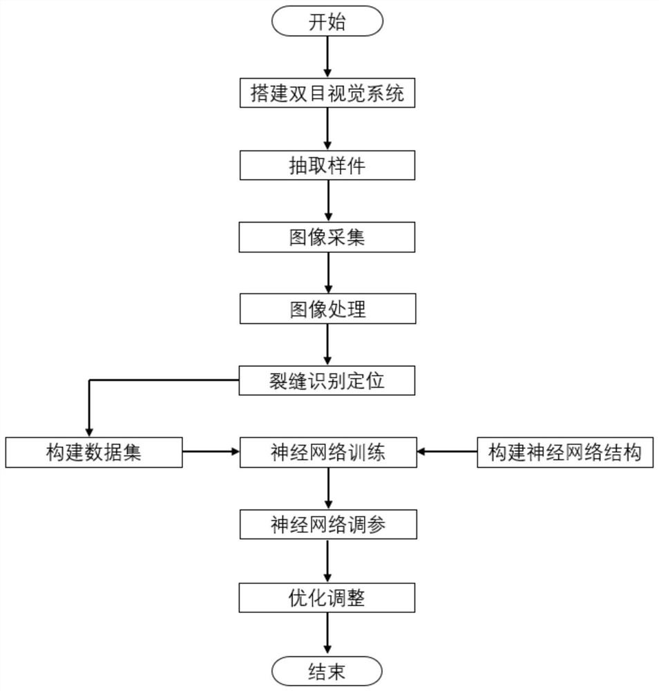
[0050] like figure 1 As shown, this embodiment provides a binocular vision-based method for identifying and locating cracks in die forgings and improving, including the following steps:

[0051] 1) The binocular vision system is used to obtain the image data of several historical die forgings with cracks, specifically:

[0052] 1.1) Build a binocular vision system, including left camera, left lens, right camera, right camera, fixed bracket, trigger, light source and computer.

[0053] 1.2) Select a camera in the binocular vision system as the main camera to collect images of several historical die forgings with cracks, and obtain image data of several historical die forgings with cracks.

[0054] Specifically, it is found from several historical die forgings that the surface contains historical die forgings with cracks due to material properties, processes and molds. A historical die forging with cracks may include one or more cracks. The network can be effectively trained, ...

Embodiment 2

[0088] This embodiment provides a binocular vision-based crack identification, positioning and improvement system for die forgings, including:

[0089] The data set building module is used to construct a neural network data set for crack identification and localization based on the image data of several historical die forgings with cracks and their corresponding crack coordinates and the causes of cracks.

[0090] The identification module is used to obtain the image data of the die forging to be identified, process it, and input it into the constructed neural network data set to determine the crack coordinates and the crack type of the to-be-identified die forging.

Embodiment 3

[0092] This embodiment provides a processing device corresponding to the binocular vision-based crack identification, positioning and improvement method for die forgings provided in Embodiment 1, and the processing device may be a processing device for a client, such as a mobile phone, a notebook computer, a tablet computer, desktop computer, etc., to execute the method of Embodiment 1.

[0093] The processing device includes a processor, a memory, a communication interface and a bus, and the processor, the memory and the communication interface are connected through the bus to complete mutual communication. A computer program that can be run on the processing device is stored in the memory, and when the processing device runs the computer program, the binocular vision-based crack identification, positioning and improvement method for a die forging provided in Embodiment 1 is executed.

[0094] In some implementations, the memory may be a high-speed random access memory (RAM: ...


PUM


Abstract

The invention relates to a die forging crack identification positioning and improvement method based on binocular vision, and the method is characterized in that the method comprises the steps: constructing a neural network data set for crack identification positioning based on the image data of a plurality of historical die forgings containing cracks, the corresponding crack coordinates and the crack generation reasons; image data of the to-be-recognized die forging is obtained, processed and then input into the constructed neural network data set, and the crack coordinates and the crack type of the to-be-recognized die forging are determined, the method can quickly find out the reason most likely to cause cracks to be generated in the die forging, and the method can be widely applied to the field of die forging defect recognition.

Description

technical field [0001] The invention relates to the field of die forging defect identification, in particular to a binocular vision-based crack identification, positioning and improvement method for a die forging. Background technique [0002] In the production process of die forgings, due to material properties, forging process and mold and other issues, it will lead to problems such as cracks in die forgings. Cracks in die forgings will seriously affect the quality of products, and with the increase of cracks, it will cause problems such as safety in the production process. Therefore, it is necessary to identify and locate the cracks of the die forgings. After the cracks are identified and located, the causes of the cracks can be found out accurately and efficiently, so as to avoid the cracks. [0003] At present, most of the methods are based on the experience of employees to find the problem, but this method cannot guarantee the accuracy and efficiency of the results. I...

Claims


Application Information

Patent Timeline
Patent Type & Authority Applications(China)
IPC IPC(8): G06T7/00G06N3/04G06N3/08G06T5/00G06T7/136
CPCG06T7/0004G06T7/136G06N3/08G06T2207/10004G06T2207/20021G06T2207/20081G06T2207/20084G06T2207/30116G06N3/045G06T5/92G06T5/70Y02P90/30
Inventor 刘志峰刘子晨赵永胜陈建洲
Owner BEIJING UNIV OF TECH
Learn More