
A method, device, equipment and medium for stress detection of structural components

A technology for structural components and stress detection, applied in the field of computers, can solve the problems of long time consumption, increase the difficulty of operation, and difficult to reflect the stress state of metal structures, and achieve the effect of high precision and accuracy

Active Publication Date: 2022-08-09
HUNAN UNIV
View PDF0 Cites 0 Cited by
  • Summary
  • Abstract
  • Description
  • Claims
  • Application Information

AI Technical Summary

Problems solved by technology

However, conventional nondestructive testing techniques have many disadvantages
First, the general non-destructive testing mainly focuses on the key parts of the structure, and it is difficult to reflect the overall stress state of the metal structure, especially for steel structures with large dimensions, some important measurement points are difficult to reach with large equipment, which increases the difficulty of the operation , which also poses a threat to the safety of testing personnel; second, the use of conventional stress detection methods takes a long time to detect, which is not conducive to places with high requirements for normal operations; third, some conventional stress detection methods are only applicable to those with Iron and steel structures with ferromagnetic properties, such as metal magnetic memory detection methods, cannot meet the requirements for stress detection of most structures at the same time

Method used


Image

  • A method, device, equipment and medium for stress detection of structural components
  • A method, device, equipment and medium for stress detection of structural components
  • A method, device, equipment and medium for stress detection of structural components

Examples


Embodiment Construction

[0047] The technical solutions in the embodiments of the present invention will be clearly and completely described below with reference to the accompanying drawings in the embodiments of the present invention. Obviously, the described embodiments are only a part of the embodiments of the present invention, but not all of the embodiments. Based on the embodiments of the present invention, all other embodiments obtained by those of ordinary skill in the art without creative efforts shall fall within the protection scope of the present invention.

[0048] There are many shortcomings in the current conventional NDT techniques. First, the general non-destructive testing mainly detects the key parts of the structure, and it is difficult to reflect the overall stress state of the metal structure, especially for the steel structure with large dimensions, some important measurement points are difficult to reach with large equipment, which increases the difficulty of operation. , and a...


PUM


Abstract

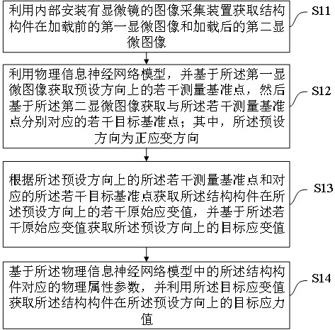
The present application discloses a stress detection method for a structural member, which relates to the field of computer technology. The method includes: acquiring a first microscopic image of a structural member before loading and a second microscopic image after loading by using an image acquisition device with a microscope installed inside. image; using the physical information neural network model, and based on the first microscopic image to obtain a number of measurement reference points in a preset direction, and then obtain a number of target reference points based on the second microscopic image; according to a number of measurement reference points in the preset direction and several target reference points to obtain several original strain values ​​of the structural member in the preset direction, and obtain the target strain value in the preset direction based on several original strain values; based on the physical attribute parameters corresponding to the structural member in the physical information neural network model , and use the target strain value to obtain the target stress value of the structural member in the preset direction. The stress state of structural members of various materials can be quickly detected by the above method.

Description

technical field [0001] The present invention relates to the field of computer technology, in particular to a method, device, equipment and medium for stress detection of structural components. Background technique [0002] At present, steel components and concrete materials will generate stress in the process of preparation, processing and use, and steel components and concrete structures are the most common structural forms in buildings, bridges and oil and gas pipelines, and have been widely used in engineering practice. In addition, the key stressed members and components of the structure will be affected by loads, material properties and environmental changes during construction, operation and maintenance. If the actual stress state is inconsistent with the design stress, the operating stress reaches or even exceeds the design limit, which may affect the The safety of the engineering structure poses a threat. Therefore, the safety of the structure has an important impact...

Claims


Application Information

Patent Timeline
Patent Type & Authority Patents(China)
IPC IPC(8): G06T7/00G06N3/04G06N3/08G01B11/16G01L1/24
CPCG06T7/0004G06N3/08G01B11/16G01L1/24G06T2207/10056G06T2207/20081G06T2207/20084G06T2207/30136G06N3/045
Inventor 王维吴智博邓露史鹏褚鸿鹄
Owner HUNAN UNIV
Learn More